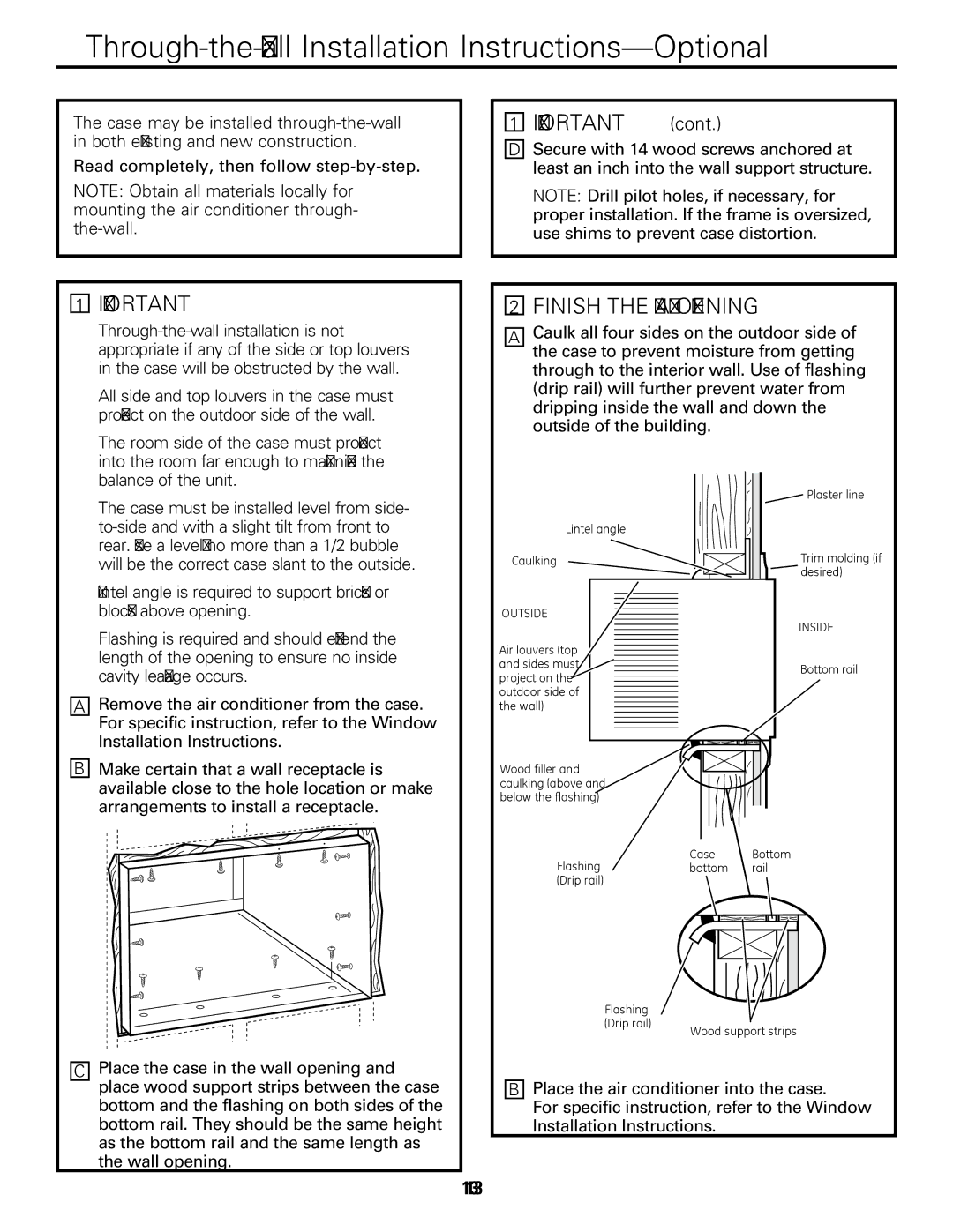
AEM25, AEQ25 specifications
The GE AEQ25 and AEM25 are advanced aircraft engines that exemplify General Electric's commitment to innovation and efficiency in aviation technology. These engines are designed to power a range of medium-range aircraft, with a focus on providing superior performance, reliability, and sustainability.One of the standout features of the AEQ25 and AEM25 engines is their state-of-the-art turbofan design. The engines incorporate advanced aerodynamics that enhance fuel efficiency while delivering powerful thrust. This turbofan architecture allows for a significant reduction in fuel consumption compared to older engine models, aligning with global efforts to lower carbon emissions in the aviation industry.
The AEQ25 and AEM25 engines utilize cutting-edge materials and manufacturing techniques. Timeless superalloys and composite materials are strategically employed to endure high temperatures and reduce weight. This combination not only enhances performance but also contributes to overall maintenance efficiency. The engines' design includes modular components, allowing for easy inspection and repairs, which minimizes downtime for aircraft operators and enhances the operational readiness of fleets.
A noteworthy technological advancement in these engine models is the introduction of digital monitoring and analytics capabilities. With integrated sensors, the AEQ25 and AEM25 engines provide real-time data on performance metrics, allowing for predictive maintenance. This technology helps operators anticipate potential issues before they become significant problems, ensuring that aircraft remain in optimal operating condition.
In terms of noise reduction, the AEQ25 and AEM25 engines are engineered to comply with stringent regulatory standards. Acoustic liners and optimized fan designs contribute to significantly lower noise levels during takeoff and landing, minimizing the impact on surrounding communities. This focus on noise abatement is increasingly essential as airports strive to balance growth with community concerns.
The AEQ25 and AEM25 engines are also designed with future sustainability in mind. They are compatible with sustainable aviation fuels (SAFs), further enhancing their environmental credentials. These bio-derived fuels can significantly reduce lifecycle greenhouse gas emissions, making these engines a preferred choice for environmentally conscious airlines.
Overall, the GE AEQ25 and AEM25 engines represent a blend of innovative technology, efficiency, and sustainability, poised to meet the demands of modern air travel while paving the way for a greener future in aviation. With their reliable performance, reduced operational costs, and commitment to environmental stewardship, these engines are set to play a crucial role in the evolving landscape of the aerospace industry.

