2. Installation
2.7 DeviceNet Board Installation
Following two types can be used for the fieldbus I/O option DeviceNet.
-
-
2.7.1 Board Appearance
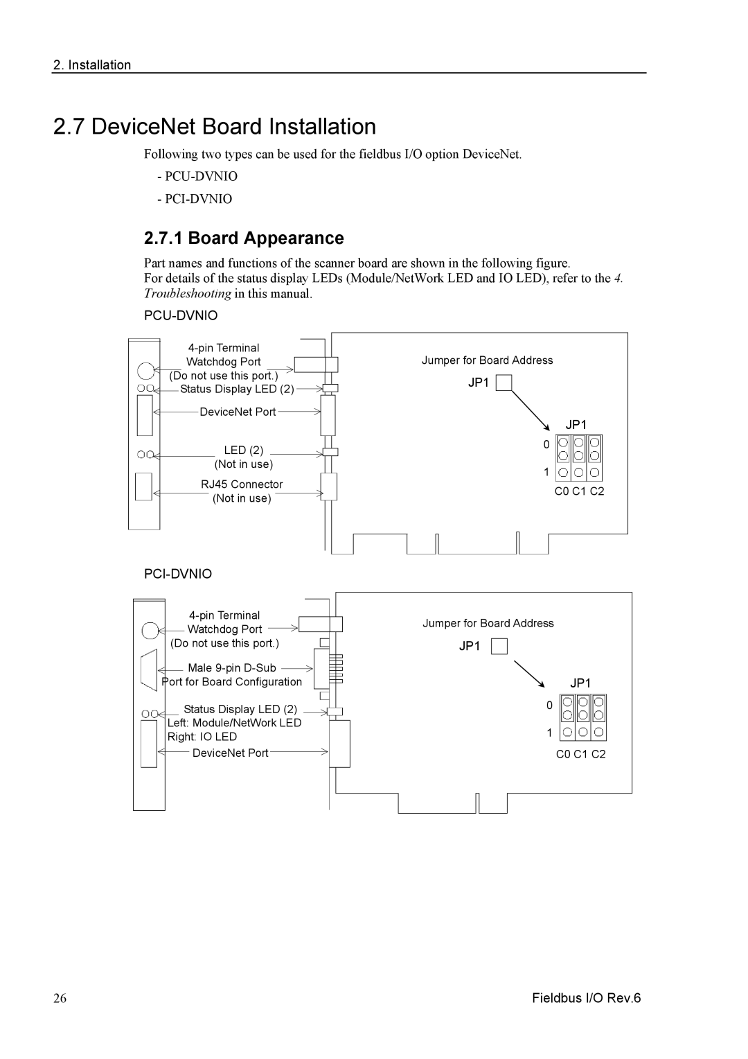
Part names and functions of the scanner board are shown in the following figure.
For details of the status display LEDs (Module/NetWork LED and IO LED), refer to the 4. Troubleshooting in this manual.
PCU-DVNIO
Jumper for Board Address | ||
Watchdog Port | ||
(Do not use this port.) | JP1 | |
Status Display LED (2) | ||
| ||
DeviceNet Port | JP1 | |
| ||
LED (2) | 0 | |
| ||
(Not in use) | 1 | |
RJ45 Connector | ||
C0 C1 C2 | ||
(Not in use) | ||
|
PCI-DVNIO
Jumper for Board Address | ||
Watchdog Port | ||
| ||
(Do not use this port.) | JP1 | |
Male |
| |
Port for Board Configuration | JP1 | |
Status Display LED (2) | 0 | |
Left: Module/NetWork LED | 1 | |
Right: IO LED | ||
| ||
DeviceNet Port | C0 C1 C2 |
26 | Fieldbus I/O Rev.6 |