2. Installation
2.6 EtherNet/IP Network Construction
Network Configuration
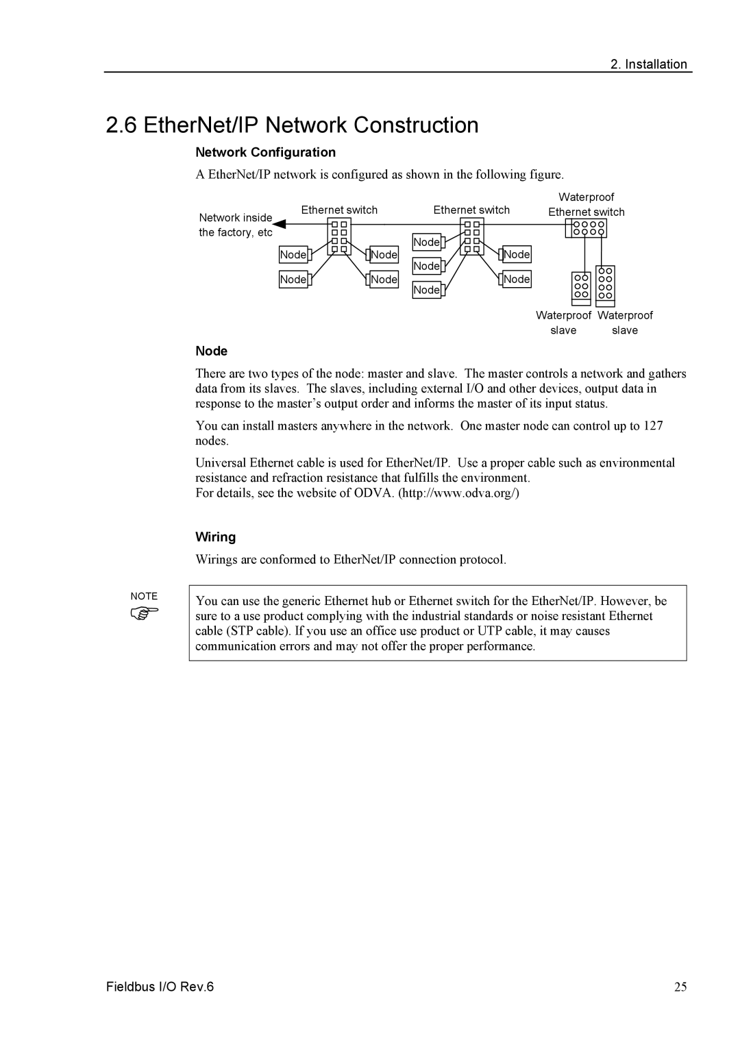
A EtherNet/IP network is configured as shown in the following figure.
| Ethernet switch | Ethernet switch | Waterproof | ||
Network inside | Ethernet switch | ||||
|
|
|
|
| |
the factory, etc |
|
| Node |
|
|
|
|
|
|
| |
| Node | Node | Node |
|
|
|
|
| Node |
|
|
| Node | Node | Node |
|
|
|
|
| Node |
|
|
|
|
|
| Waterproof Waterproof | |
|
|
|
| slave | slave |
Node
NOTE
)
There are two types of the node: master and slave. The master controls a network and gathers data from its slaves. The slaves, including external I/O and other devices, output data in response to the master’s output order and informs the master of its input status.
You can install masters anywhere in the network. One master node can control up to 127 nodes.
Universal Ethernet cable is used for EtherNet/IP. Use a proper cable such as environmental resistance and refraction resistance that fulfills the environment.
For details, see the website of ODVA. (http://www.odva.org/)
Wiring
Wirings are conformed to EtherNet/IP connection protocol.
You can use the generic Ethernet hub or Ethernet switch for the EtherNet/IP. However, be sure to a use product complying with the industrial standards or noise resistant Ethernet cable (STP cable). If you use an office use product or UTP cable, it may causes communication errors and may not offer the proper performance.
Fieldbus I/O Rev.6 | 25 |
