2. Installation
Procedure for Modifying and Installing Communication Cables
The following procedure explains how to modify and install a Woodhead
Follow the steps described below to modify communication cables and connect them to the connector.
Be careful not to injure your hands or fingers on any sharp blades or tools used to modify the cable.
Use appropriate blades and/or other tools to modify the cable. Using
CAUTION | inappropriate blades and/or other tools may result in bodily injury and/or | |
equipment damage. | ||
|
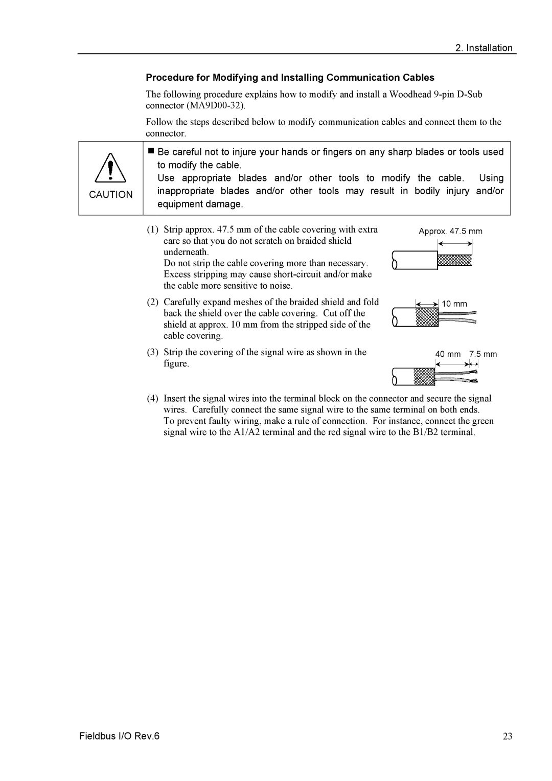
(1)Strip approx. 47.5 mm of the cable covering with extra care so that you do not scratch on braided shield underneath.
Do not strip the cable covering more than necessary. Excess stripping may cause
(2)Carefully expand meshes of the braided shield and fold back the shield over the cable covering. Cut off the shield at approx. 10 mm from the stripped side of the cable covering.
(3)Strip the covering of the signal wire as shown in the figure.
Approx. 47.5 mm


 10 mm
10 mm
40 mm 7.5 mm
(4)Insert the signal wires into the terminal block on the connector and secure the signal wires. Carefully connect the same signal wire to the same terminal on both ends. To prevent faulty wiring, make a rule of connection. For instance, connect the green signal wire to the A1/A2 terminal and the red signal wire to the B1/B2 terminal.
Fieldbus I/O Rev.6 | 23 |