1. Introduction
1. Introduction
1.1 Overview of Fieldbus I/O
The Fieldbus I/O option is an integrated I/O system that supports DeviceNet, PROFIBUS DP, and EtherNet/IP fieldbuses.
A fieldbus is a standard of signal communications between field devices operating in a factory (sensor, actuator, robot controller, etc.) and controller (PLC or robot controller) using serial communications. Compared to signal communications using analog signals, a fieldbus has the following features:
•Access to signals from multiple devices and multiple data from each device using one cable.
•Precise signal transmission since there is no need for A/D conversion and D/A conversion.
•Less wiring costs, including signal relay board costs and installation area due to several dozen (or a hundred) devices connected on one fieldbus.
•More flexible modification and expansion of a system because multiple devices are simply added to one fieldbus without additional wiring.
•Slave devices can transmit
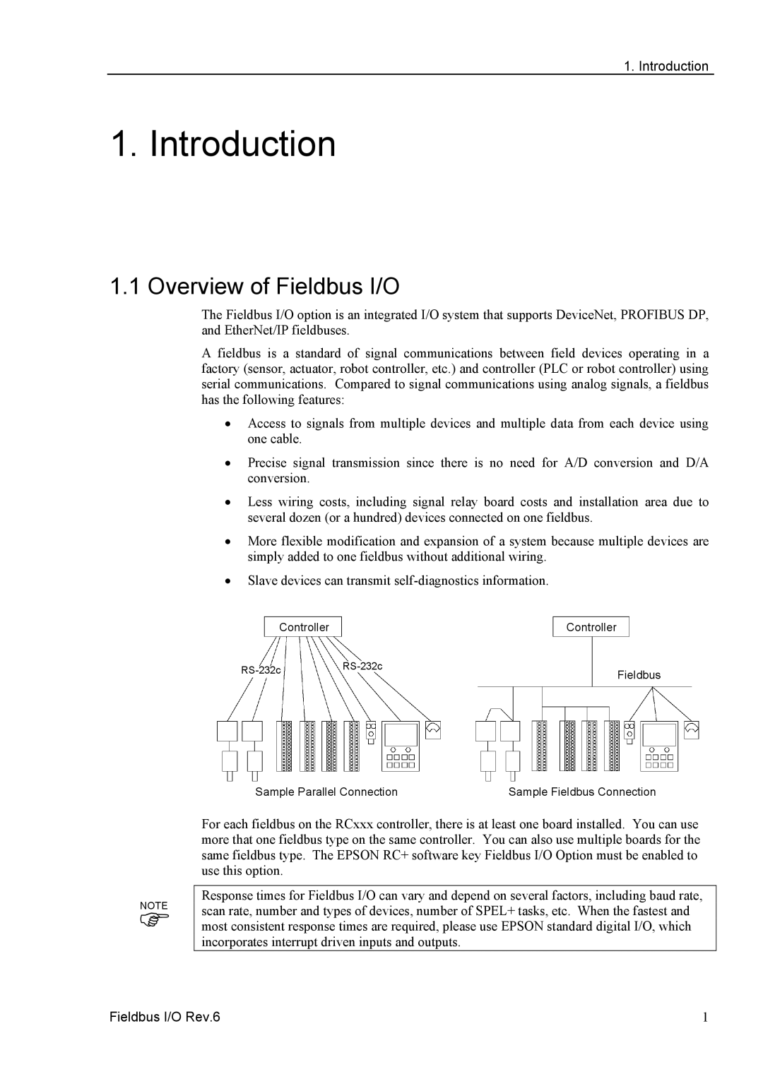
ControllerController
Fieldbus | ||
| ||
|
|
NOTE
)
Sample Parallel Connection | Sample Fieldbus Connection |
For each fieldbus on the RCxxx controller, there is at least one board installed. You can use more that one fieldbus type on the same controller. You can also use multiple boards for the same fieldbus type. The EPSON RC+ software key Fieldbus I/O Option must be enabled to use this option.
Response times for Fieldbus I/O can vary and depend on several factors, including baud rate, scan rate, number and types of devices, number of SPEL+ tasks, etc. When the fastest and most consistent response times are required, please use EPSON standard digital I/O, which incorporates interrupt driven inputs and outputs.
Fieldbus I/O Rev.6 | 1 |