2. Installation
It is recommended that a
Pin assignment (9-pin D-Sub)
Pin No. | Signal | Assignment |
1 | Shield | Shield / Protective ground |
2 | M24 | Ground of output voltage (24 V) |
3 | Data line B | |
4 | Repeater control signal (directional control) | |
5 | DGND | Communications power supply (5 V) |
6 | VP | Supply voltage to terminating resistor (P5V) |
7 | P24 | Output voltage (24 V) |
8 | Data line A | |
9 |
| Repeater control signal (directional control) |
Use pins 2 and 7 for connecting a maintenance device without any power supply.
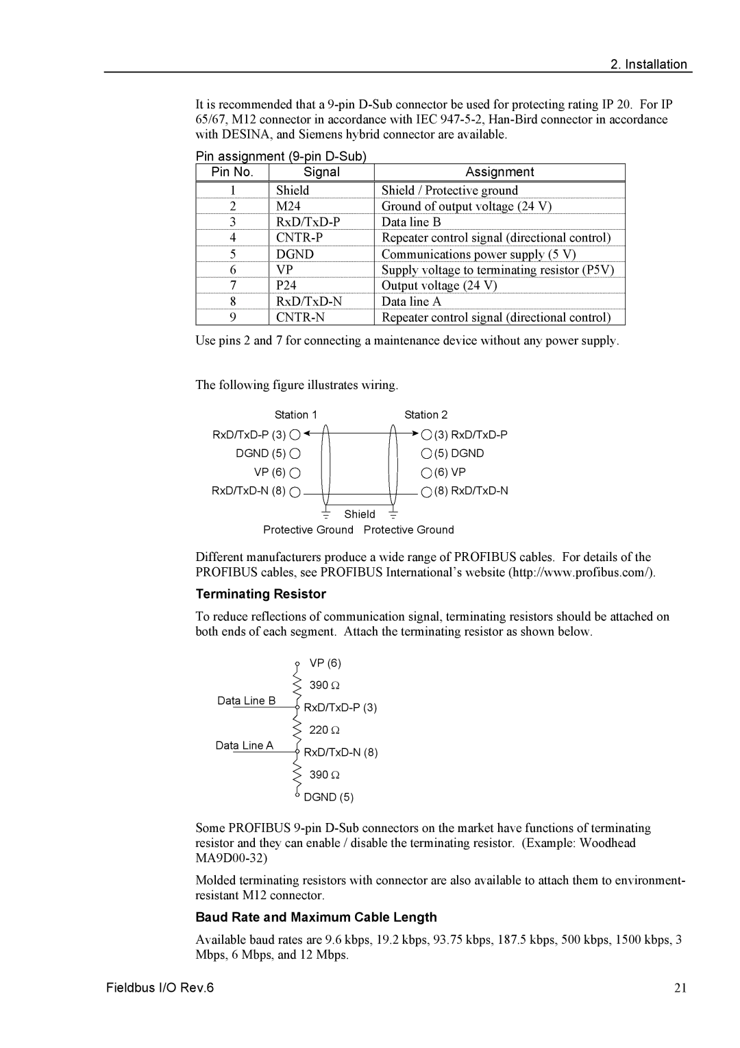
The following figure illustrates wiring.
Station 1 | Station 2 |
|
(3) | ||
DGND (5) | (5) DGND | |
VP (6) | (6) | VP |
(8) | ||
Shield |
| |
Protective Ground | Protective Ground | |
Different manufacturers produce a wide range of PROFIBUS cables. For details of the PROFIBUS cables, see PROFIBUS International’s website (http://www.profibus.com/).
Terminating Resistor
To reduce reflections of communication signal, terminating resistors should be attached on both ends of each segment. Attach the terminating resistor as shown below.
| VP (6) |
| 390 Ω |
Data Line B | |
| |
| 220 Ω |
Data Line A | |
| |
| 390 Ω |
| DGND (5) |
Some PROFIBUS
Molded terminating resistors with connector are also available to attach them to environment- resistant M12 connector.
Baud Rate and Maximum Cable Length
Available baud rates are 9.6 kbps, 19.2 kbps, 93.75 kbps, 187.5 kbps, 500 kbps, 1500 kbps, 3 Mbps, 6 Mbps, and 12 Mbps.
Fieldbus I/O Rev.6 | 21 |