4. Troubleshooting (DeviceNet)
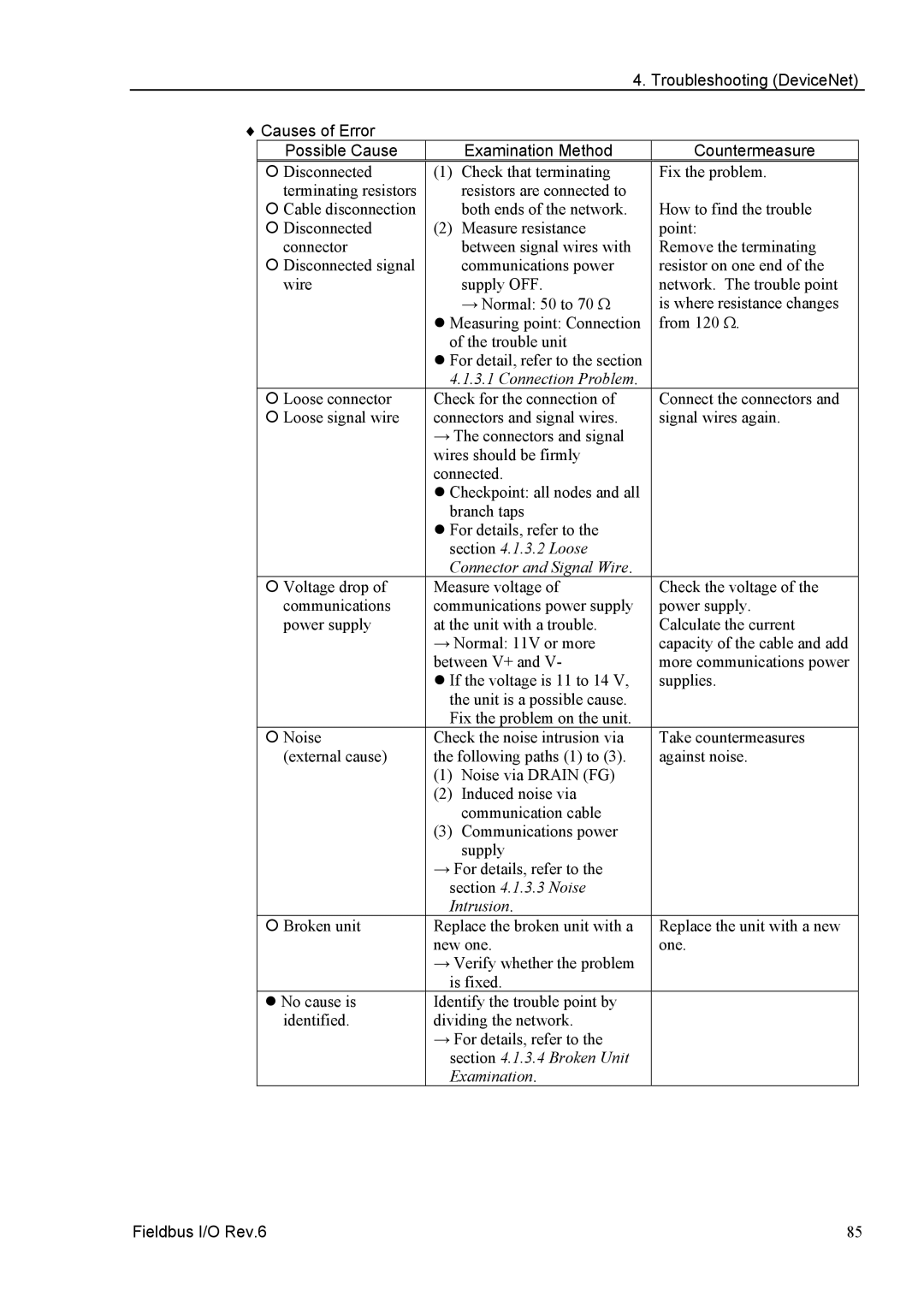
♦ Causes of Error |
|
| Countermeasure | |
| Possible Cause |
| Examination Method | |
| { Disconnected | (1) | Check that terminating | Fix the problem. |
| terminating resistors |
| resistors are connected to |
|
| { Cable disconnection |
| both ends of the network. | How to find the trouble |
| { Disconnected | (2) | Measure resistance | point: |
| connector |
| between signal wires with | Remove the terminating |
| { Disconnected signal |
| communications power | resistor on one end of the |
| wire |
| supply OFF. | network. The trouble point |
→Normal: 50 to 70 Ω is where resistance changes
z Measuring point: Connection from 120 Ω. of the trouble unit
| z For detail, refer to the section |
| |
| 4.1.3.1 Connection Problem. | Connect the connectors and | |
{ Loose connector | Check for the connection of | ||
{ Loose signal wire | connectors and signal wires. | signal wires again. | |
| → The connectors and signal |
| |
| wires should be firmly |
| |
| connected. |
| |
| z Checkpoint: all nodes and all |
| |
| branch taps |
| |
| z For details, refer to the |
| |
| section 4.1.3.2 Loose |
| |
| Connector and Signal Wire. | Check the voltage of the | |
{ Voltage drop of | Measure voltage of | ||
communications | communications power supply | power supply. | |
power supply | at the unit with a trouble. | Calculate the current | |
| → Normal: 11V or more | capacity of the cable and add | |
| between V+ and V- | more communications power | |
| z If the voltage is 11 to 14 V, | supplies. | |
| the unit is a possible cause. |
| |
| Fix the problem on the unit. | Take countermeasures | |
{ Noise | Check the noise intrusion via | ||
(external cause) | the following paths (1) to (3). | against noise. | |
| (1) | Noise via DRAIN (FG) |
|
| (2) | Induced noise via |
|
|
| communication cable |
|
| (3) | Communications power |
|
|
| supply |
|
| → For details, refer to the |
| |
| section 4.1.3.3 Noise |
| |
| Intrusion. | Replace the unit with a new | |
{ Broken unit | Replace the broken unit with a | ||
| new one. | one. | |
| → Verify whether the problem |
| |
| is fixed. |
| |
z No cause is | Identify the trouble point by |
| |
identified. | dividing the network. |
| |
| → For details, refer to the |
| |
| section 4.1.3.4 Broken Unit |
| |
| Examination. |
| |
Fieldbus I/O Rev.6 | 85 |