2. Installation
Total Drop Line Length
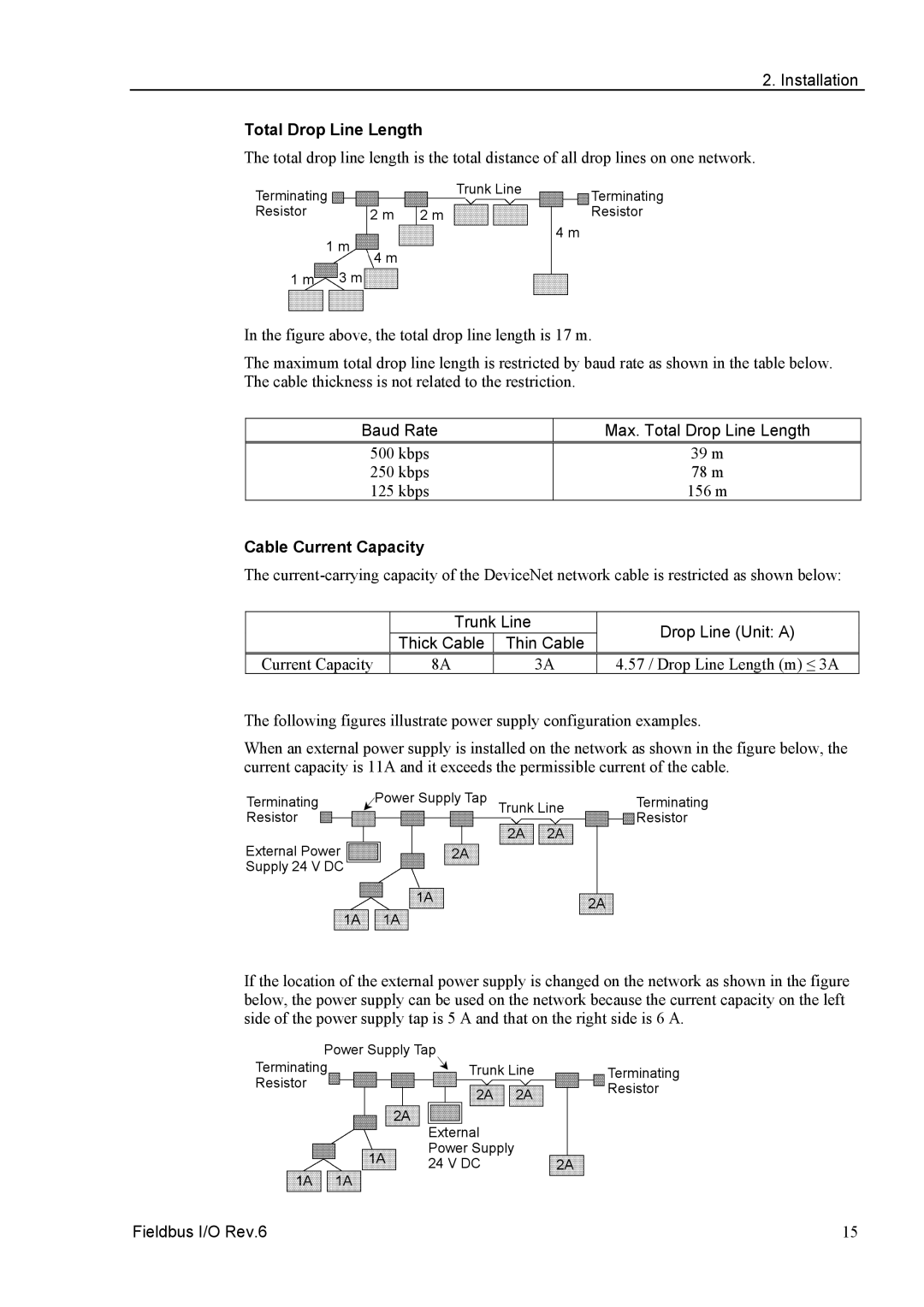
The total drop line length is the total distance of all drop lines on one network.
Terminating |
| Trunk Line | Terminating |
|
| ||
Resistor | 2 m 2 m |
| Resistor |
1 m |
| 4 m | |
|
| ||
| 4 m |
|
|
1 m | 3 m |
|
|
In the figure above, the total drop line length is 17 m.
The maximum total drop line length is restricted by baud rate as shown in the table below. The cable thickness is not related to the restriction.
Baud Rate | Max. Total Drop Line Length |
500 kbps | 39 m |
250 kbps | 78 m |
125 kbps | 156 m |
Cable Current Capacity
The
| Trunk Line | |
| Thick Cable | Thin Cable |
Current Capacity | 8A | 3A |
Drop Line (Unit: A)
4.57 / Drop Line Length (m) ≤ 3A
The following figures illustrate power supply configuration examples.
When an external power supply is installed on the network as shown in the figure below, the current capacity is 11A and it exceeds the permissible current of the cable.
Terminating | Power Supply Tap | Trunk Line | Terminating | |
Resistor |
| Resistor | ||
| 2A | 2A | ||
External Power |
|
| ||
2A |
|
|
| |
Supply 24 V DC |
|
|
|
|
| 1A |
|
| 2A |
1A | 1A |
|
| |
|
|
| ||
If the location of the external power supply is changed on the network as shown in the figure below, the power supply can be used on the network because the current capacity on the left side of the power supply tap is 5 A and that on the right side is 6 A.
Power Supply Tap |
|
| ||
Terminating |
| Trunk Line | Terminating | |
Resistor |
| 2A | 2A | Resistor |
|
| |||
|
|
| ||
|
| 2A |
|
|
|
| External |
|
|
| 1A | Power Supply |
|
|
| 24 V DC |
| 2A | |
1A | 1A |
| ||
|
|
| ||
Fieldbus I/O Rev.6 | 15 |