2. Installation
(2)Carefully expand the meshes of the braided shield. Under the braided shield, there is one exposed bare twisted shield wire other than the signal wires and power wires that are wrapped with aluminum tape. The shield wire is slightly harder than the mesh.
(3)Cut off the expanded braided shield and remove the aluminum tape around the signal wires and power wires. Then, strip the insulation from the signal wires and power wires for a length sufficient to connect them to crimp terminals.
Twist each stripped signal wire and power wire.
(4)Set the crimp terminal on the stripped part of the wire and crimp it with a crimp tool. The following crimping terminals are recommended products.
NICHIFU TC series
Shield Wire
Peel the coverings in enough length to connect the wires to crimping terminals.
Crimping
Terminal
NOTE
)
| Model Number | Specifications |
|
| Special Tool |
| TMEV | For Thin Cable |
|
| |
| TMEV | For Thick Cable (power wire) |
| ||
| TMEV | For Thick Cable (signal wire) |
|
| |
| Phoenix Contact AI series |
|
|
|
|
| Model Number | Specifications |
|
| Special Tool |
| AI | For Thin Cable (power cable) |
|
| |
| AI | For Thin Cable (signal wire) | CRIMPFOX UD6 | ||
| AI | For Thick Cable (signal wire) | |||
|
|
| |||
| AI | For Thick Cable (signal wire) |
|
| |
(5) Wrap or cover the cable with vinyl tape or | |||||
| tubing. |
|
|
|
|
Loosen the screws securing the cables on the connector. If the screws are not loosened, the wires go into different openings on the rear of connector instead of the correct openings and the wires cannot be secured.
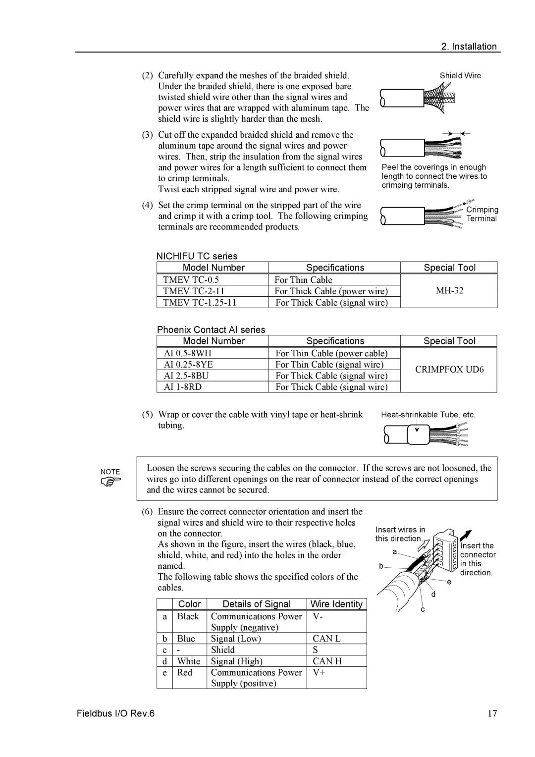
(6)Ensure the correct connector orientation and insert the signal wires and shield wire to their respective holes on the connector.
As shown in the figure, insert the wires (black, blue, shield, white, and red) into the holes in the order named.
The following table shows the specified colors of the cables.
| Color | Details of Signal | Wire Identity |
a | Black | Communications Power | V- |
|
| Supply (negative) |
|
b | Blue | Signal (Low) | CAN L |
c | - | Shield | S |
d | White | Signal (High) | CAN H |
e | Red | Communications Power | V+ |
|
| Supply (positive) |
|
Insert wires in |
| |
this direction. | Insert the | |
a | ||
connector | ||
b | in this | |
| direction. | |
| e | |
| d | |
c |
|
Fieldbus I/O Rev.6 | 17 |