4. Troubleshooting (PROFIBUS DP)
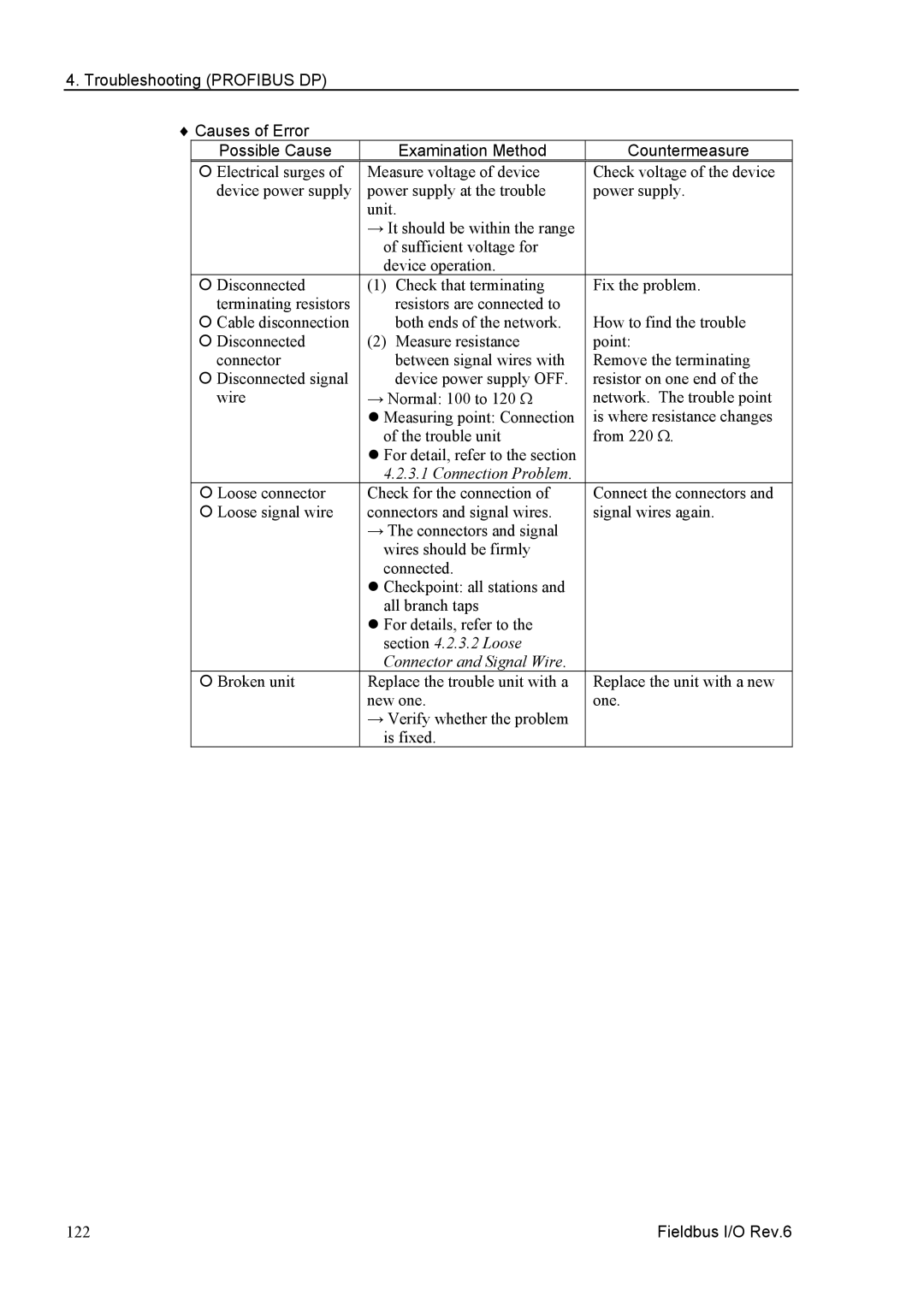
♦ Causes of Error
Possible Cause |
| Examination Method | Countermeasure |
{ Electrical surges of | Measure voltage of device | Check voltage of the device | |
device power supply | power supply at the trouble | power supply. | |
| unit. |
| |
| → It should be within the range |
| |
| of sufficient voltage for |
| |
| device operation. |
| |
{ Disconnected | (1) | Check that terminating | Fix the problem. |
terminating resistors |
| resistors are connected to |
|
{ Cable disconnection |
| both ends of the network. | How to find the trouble |
{ Disconnected | (2) | Measure resistance | point: |
connector |
| between signal wires with | Remove the terminating |
{ Disconnected signal |
| device power supply OFF. | resistor on one end of the |
wire | → Normal: 100 to 120 Ω | network. The trouble point | |
| z Measuring point: Connection | is where resistance changes | |
| of the trouble unit | from 220 Ω. | |
| z For detail, refer to the section |
| |
| 4.2.3.1 Connection Problem. |
| |
{ Loose connector | Check for the connection of | Connect the connectors and | |
{ Loose signal wire | connectors and signal wires. | signal wires again. | |
| → The connectors and signal |
| |
| wires should be firmly |
| |
| connected. |
| |
| z Checkpoint: all stations and |
| |
| all branch taps |
| |
| z For details, refer to the |
| |
| section 4.2.3.2 Loose |
| |
| Connector and Signal Wire. |
| |
{ Broken unit | Replace the trouble unit with a | Replace the unit with a new | |
| new one. | one. | |
| → Verify whether the problem |
| |
| is fixed. |
| |
122 | Fieldbus I/O Rev.6 |