ASTAT
Power Supply Board Replacement
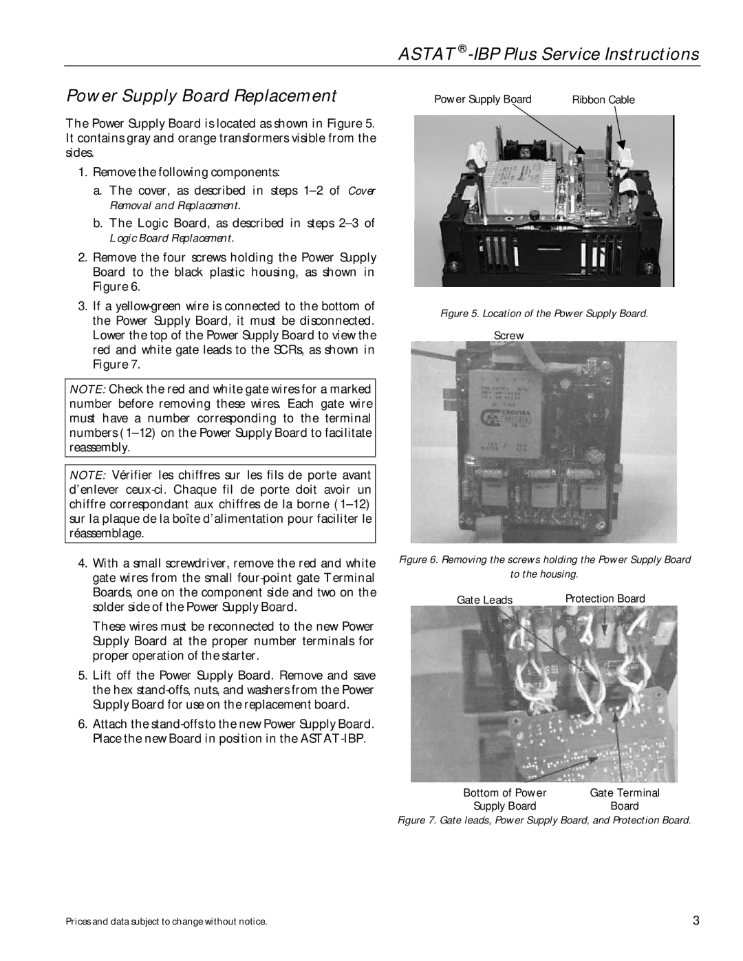
The Power Supply Board is located as shown in Figure 5. It contains gray and orange transformers visible from the sides.
1.Remove the following components:
a.The cover, as described in steps
b.The Logic Board, as described in steps
2.Remove the four screws holding the Power Supply Board to the black plastic housing, as shown in Figure 6.
3.If a
NOTE: Check the red and white gate wires for a marked number before removing these wires. Each gate wire must have a number corresponding to the terminal numbers
NOTE: Vérifier les chiffres sur les fils de porte avant d’enlever
4.With a small screwdriver, remove the red and white gate wires from the small
These wires must be reconnected to the new Power Supply Board at the proper number terminals for proper operation of the starter.
5.Lift off the Power Supply Board. Remove and save the hex
6.Attach the
Power Supply Board | Ribbon Cable |
Figure 5. Location of the Power Supply Board.
Screw
Figure 6. Removing the screws holding the Power Supply Board
to the housing.
Gate Leads | Protection Board |
Bottom of Power | Gate Terminal |
Supply Board | Board |
Figure 7. Gate leads, Power Supply Board, and Protection Board.
Prices and data subject to change without notice. | 3 |
