POWER LEADER™ Ethernet Gateway
Chapter 5 – Errors and Diagnostic Messages
Chapter 5 – Diagnostic Messages and Errors
|
|
The Ethernet Gateway can be set to send diagnostic messages to the RS232 port to be displayed on a
terminal (see Chapter 3). These diagnostic messages can be very useful in tracking down errors in configuration or device addressing.
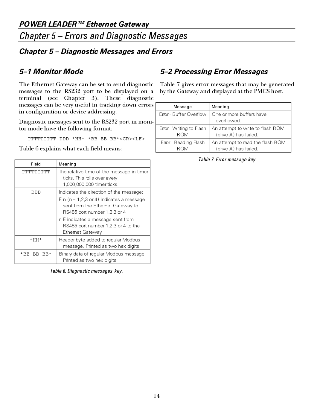
Diagnostic messages sent to the RS232 port in moni- tor mode have the following format:
Table 6 explains what each field means:
Field |
| Meaning |
|
|
|
|
| The relative time of the message in timer |
|
| ticks. This rolls over every |
|
| 1,000,000,000 timer ticks. |
|
| Indicates the direction of the message: |
|
| |
|
| sent from the Ethernet Gateway to |
|
| RS485 port number 1,2,3 or 4 |
|
| |
|
| RS485 port number 1,2,3 or 4 to the |
|
| Ethernet Gateway |
|
|
|
|
| Header byte added to regular Modbus |
|
| message. Printed as two hex digits. |
|
| Binary data of regular Modbus message. |
|
| Printed as two hex digits. |
|
|
|
| Table 6. Diagnostic messages key. | |
Table 7 gives error messages that may be generated by the Gateway and displayed at the PMCS host.
Message | Meaning |
|
|
Error - Buffer Overflow | One or more buffers have |
| overflowed. |
Error - Writing to Flash | An attempt to write to flash ROM |
ROM | (drive A) has failed. |
|
|
Error - Reading Flash | An attempt to read the flash ROM |
ROM | (drive A) has failed. |
Table 7. Error message key.
14