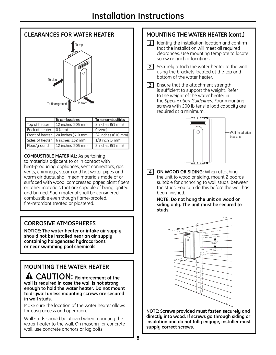
GN75ENSRSA, GN94ENSRSA, GP94ENSRSA specifications
The GE GN94ENSRSA, GP94ENSRSA, and GN75ENSRSA represent a new generation of advanced gas turbines developed by General Electric (GE) for use in power generation applications. These models are designed for efficiency, reliability, and environmental sustainability, making them ideal for both industrial and utility-scale projects.A hallmark of these turbines is their high efficiency. GE has implemented cutting-edge aerodynamics and materials technology to create a combustion process that maximizes energy extraction while minimizing fuel consumption. The GN94ENSRSA and GP94ENSRSA models specifically feature advanced compressor designs that increase air intake and compression ratio, enhancing overall performance.
The turbines incorporate GE's Digital Wind Farm technology, which utilizes advanced data analytics and machine learning to optimize operational efficiency. This technology allows for predictive maintenance, reducing downtime and operational costs. Users can monitor turbine performance in real-time, making adjustments as needed to boost output and efficiency.
Another significant feature is the flexible fuel capability. The GN94ENSRSA and GP94ENSRSA can operate with various fuel types, including natural gas, biogas, and hydrogen, making them versatile solutions for a range of energy markets. This flexibility aligns with global trends toward cleaner energy, helping reduce carbon emissions.
Safety and reliability are at the forefront of GE's design philosophy. The turbines are equipped with multiple safety features to ensure stable operation even under extreme conditions. This includes advanced control systems that continuously monitor critical parameters and adjust operations to maintain performance and safety standards.
In terms of emissions, GE has prioritized the development of low-emission technologies. These turbines are designed to meet stringent environmental regulations, reducing nitrogen oxides (NOx) and carbon monoxide (CO) emissions through enhanced combustion technology. This commitment to environmental sustainability has made GE’s turbines a preferred choice for many energy providers looking to transition to cleaner forms of power generation.
In summary, the GE GN94ENSRSA, GP94ENSRSA, and GN75ENSRSA gas turbines exemplify the latest advancements in turbine technology. With their high efficiencies, flexible fuel options, robust safety features, and commitment to reducing emissions, these models underscore GE's leadership in the energy sector and its dedication to sustainable power solutions. As global energy demands continue to evolve, these turbines provide a reliable path forward for efficient and responsible power generation.

