
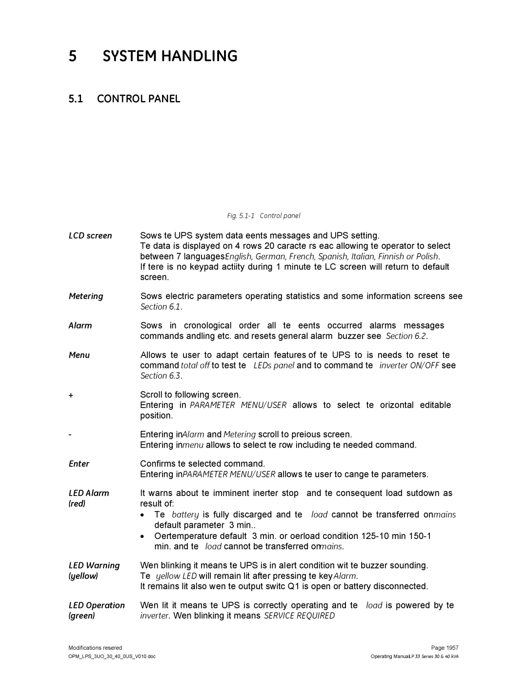
LP 33 specifications
The GE LP 33 is a cutting-edge locomotive designed and manufactured by General Electric for freight and transport companies. This model is renowned in the railway industry for its advanced technology, robustness, and efficiency. With a focus on enhancing performance while reducing environmental impact, the GE LP 33 stands out as a significant advancement in modern locomotive design.One of the primary features of the GE LP 33 is its powerful engine, which offers impressive horsepower and torque. This allows the locomotive to pull heavy loads over long distances without compromising speed or efficiency. The engine is designed with fuel efficiency in mind, reducing operational costs for rail companies while also promoting sustainable practices.
In terms of technology, the GE LP 33 is equipped with sophisticated digital controls that streamline operations and improve reliability. The locomotive's onboard diagnostics system monitors performance in real time, allowing for proactive maintenance and reducing the risk of breakdowns. This not only ensures a smoother operation but also contributes to safety on the railways.
Another key characteristic of the GE LP 33 is its aerodynamic design. The streamlined shape minimizes air resistance, allowing the locomotive to achieve higher speeds with lower fuel consumption. This design philosophy extends to the overall build of the locomotive, which utilizes lightweight yet durable materials that enhance performance without sacrificing strength.
The GE LP 33 also incorporates advanced braking systems that increase safety and reliability. The autonomous braking technology enables the locomotive to respond rapidly to changing conditions, which is critical when transporting hazardous materials or operating in congested areas. Furthermore, the locomotive is engineered to meet strict environmental regulations, with reduced emissions and noise pollution compared to older models.
The GE LP 33’s flexible configuration options make it suitable for various applications within the freight industry. It can be customized to handle different types of cargo, from bulk materials to intermodal containers. This adaptability, combined with its powerful performance, makes the GE LP 33 a versatile choice for rail operators seeking to optimize their logistics.
In summary, the GE LP 33 represents a significant milestone in locomotive technology, focusing on performance, efficiency, and environmental responsibility. Its advanced features, robust design, and innovative systems position it as a leader in modern rail transport, catering to the evolving needs of the freight industry while paving the way for a more sustainable future in transportation.