g
Digital Energy™ GT Series
3 - Operation
3.1Operation Panel
3 5
61
4 | 2 |
|
8
9
7
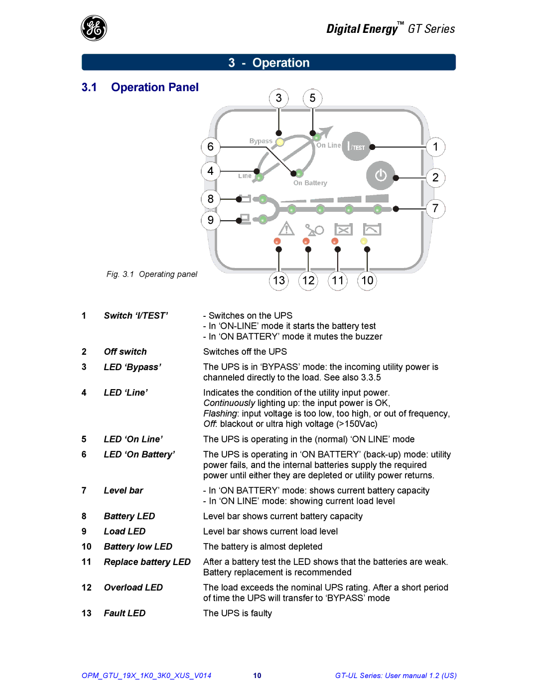
Fig. 3.1 Operating panel
13 12 11 10
1 | Switch ‘I/TEST’ | - Switches on the UPS |
|
| - In |
|
| - In ‘ON BATTERY’ mode it mutes the buzzer |
2 | Off switch | Switches off the UPS |
3 | LED ‘Bypass’ | The UPS is in ‘BYPASS’ mode: the incoming utility power is |
|
| channeled directly to the load. See also 3.3.5 |
4 | LED ‘Line’ | Indicates the condition of the utility input power. |
|
| Continuously lighting up: the input power is OK, |
|
| Flashing: input voltage is too low, too high, or out of frequency, |
|
| Off: blackout or ultra high voltage (>150Vac) |
5 | LED ‘On Line’ | The UPS is operating in the (normal) ‘ON LINE’ mode |
6LED ‘On Battery’ The UPS is operating in ‘ON BATTERY’
7 | Level bar | - In ‘ON BATTERY’ mode: shows current battery capacity |
|
| - In ‘ON LINE’ mode: showing current load level |
8 | Battery LED | Level bar shows current battery capacity |
9 | Load LED | Level bar shows current load level |
10Battery low LED The battery is almost depleted
11Replace battery LED After a battery test the LED shows that the batteries are weak.
Battery replacement is recommended
12 | Overload LED | The load exceeds the nominal UPS rating. After a short period |
|
| of time the UPS will transfer to ‘BYPASS’ mode |
13 | Fault LED | The UPS is faulty |
OPM_GTU_19X_1K0_3K0_XUS_V014 | 10 |
