Installation Instructions

CONNECTING THE DRYER TO

HOUSE VENT

RIGID METAL TRANSITION DUCT

For best drying performance, a rigid metal transition duct is recommended.

Rigid metal transition ducts reduce the risk of crushing and kinking.

UL-LISTED FLEXIBLE METAL (SEMI-RIGID) TRANSITION DUCT

If rigid metal duct cannot be used, then UL-listed flexible metal (semi-rigid) ducting can be used (Kit WX08X10077).

Never install flexible metal duct in walls, ceilings, floors or other enclosed spaces.

Total length of flexible metal duct should not exceed 8 feet (2.4 m).

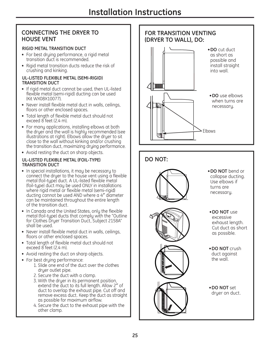
For many applications, installing elbows at both the dryer and the wall is highly recommended (see illustrations at right). Elbows allow the dryer to sit close to the wall without kinking and/or crushing the transition duct, maximizing drying performance.

Avoid resting the duct on sharp objects.

UL-LISTED FLEXIBLE METAL (FOIL-TYPE)

TRANSITION DUCT

In special installations, it may be necessary to connect the dryer to the house vent using a flexible metal (foil-type) duct. A UL-listed flexible metal (foil-type) duct may be used ONLY in installations

where rigid metal or flexible metal (semi-rigid) ducting cannot be used AND where a 4diameter can be maintained throughout the entire length of the transition duct.

In Canada and the United States, only the flexible metal (foil-type) ducts that comply with the “Outline for Clothes Dryer Transition Duct, Subject 2158A” shall be used.

Never install flexible metal duct in walls, ceilings, floors or other enclosed spaces.

Total length of flexible metal duct should not exceed 8 feet (2.4 m).

Avoid resting the duct on sharp objects.

For best drying performance:

1.Slide one end of the duct over the clothes dryer outlet pipe.

2.Secure the duct with a clamp.

3.With the dryer in its permanent position, extend the duct to its full length. Allow 2of duct to overlap the exhaust pipe. Cut off and remove excess duct. Keep the duct as straight as possible for maximum airflow.

4.Secure the duct to the exhaust pipe with the other clamp.

FOR TRANSITION VENTING (DRYER TO WALL), DO:

•DO cut duct as short as possible and install straight into wall.

•DO use elbows when turns are necessary.

Elbows

DO NOT:

•DO NOT bend or collapse ducting. Use elbows if turns are necessary.

•DO NOT use excessive exhaust length. Cut duct as short as possible.

•DO NOT crush duct against the wall.

•DO NOT set dryer on duct.

25

Page 25
Image 25
GE DPGT650, UPGT650 Connecting the Dryer to House Vent, Do not, For Transition Venting Dryer to WALL, do

DPGT650, UPGT650 specifications

The GE UPGT650 and DPGT650 are advanced gas turbine models developed by General Electric, known for their cutting-edge technology and high efficiency. Designed primarily for power generation and industrial applications, these gas turbines represent the latest in innovation and performance in the energy sector.

At the heart of the UPGT650 is its high-efficiency design that optimizes fuel consumption while reducing emissions. This gas turbine operates at a high pressure ratio, which significantly enhances its overall efficiency, making it a preferred choice for operators seeking to minimize operational costs while maximizing output. The UPGT650 boasts a fuel flexibility feature, enabling it to run on various fuels, including natural gas and liquid fuels, catering to different operational needs and geographical conditions.

The DPGT650 variant, specifically developed for applications requiring high reliability and performance in distributed power generation, offers similar efficiency benefits while providing enhanced operational flexibility. Its modular design allows for easy maintenance and upgrades, which is crucial for facilities needing to adapt to changing energy demands and regulatory environments.

Both turbine models incorporate advanced technologies such as advanced cooling systems to maintain optimal operating temperatures and enhance durability. The utilization of advanced materials in the turbine blades contributes to their ability to withstand high thermal and mechanical stress, further improving performance longevity. Additionally, the turbines are equipped with sophisticated control systems that enable operators to achieve precise load management and efficient power dispatch.

A critical characteristic of the UPGT650 and DPGT650 is their environmental performance. These turbines are engineered to meet stringent emissions standards, effectively reducing CO2 and NOx emissions. This makes them suitable for regions with strict environmental regulations, appealing to companies focused on sustainability and environmental responsibility.

In summary, the GE UPGT650 and DPGT650 gas turbines stand out in the energy landscape for their efficiency, reliability, and environmental performance. With features like fuel flexibility, advanced cooling technologies, and modular design, they are poised to meet the evolving demands of the power generation industry, driving the transition towards cleaner and more efficient energy systems.