Safety Instructions
Consumer Support Warranty Canada Warranty U.S
Operating
Clear the room, building or area of all occupants
For complete details, follow the Installation Instructions
GEAppliances.com
Your Laundry Area
Close supervision is necessary if this appliance
When Using Your Dryer
Instructions Installation
About the dryer control panel
Control Panel
Time Dry
Power
Cycles
Dry Level
My Cycles
You can change the temperature of your dry cycle
To store a MY Cycles combination of settings
To recall your stored MY Cycles combination
Wrinkle Care
Signal
About cycle options
Alerts you that the cycle is complete
Estimated Time Remaining
Installation Instructions
Lock
Screw Changing the Drum Lamp
Dryer features
Using the Drying Rack
Fabric Care Labels
Loading and using the dryer
Sorting and Loading Hints
Dry Labels
Do not touch the surface or the display with sharp objects
Safety
Care and Cleaning of the Dryer
Before YOU Begin
For Your Safety
DPGT650 and UPGT650
For GAS Models only
Minimum Clearance Other than Alcove or Closet Installation
Installation Instructions
Dryer Dimensions
Unpacking Your Dryer
Installation Instructions Location of Your Dryer
Bathroom or Bedroom Installation
Shutoff Valve
Installation Instructions Connecting a GAS Dryer
Connecting the Dryer to the GAS Supply
Connecting the Dryer to the GAS Supply
Test for Leaks
Electrical Requirements For GAS Dryers
Electrical Connection Information for Electric Dryers
For 3-wire and 4-wire Connection
Installation Instructions Connecting AN Electric Dryer
Connecting Dryer Power Cord
Grounding Instructions
For 3-wire Connection only
For 4-wire Connection only
Vent hood
Exhaust System Checklist
For best performance, separate all turns by
For Transition Venting Dryer to WALL, do
Connecting the Dryer to House Vent
Do not
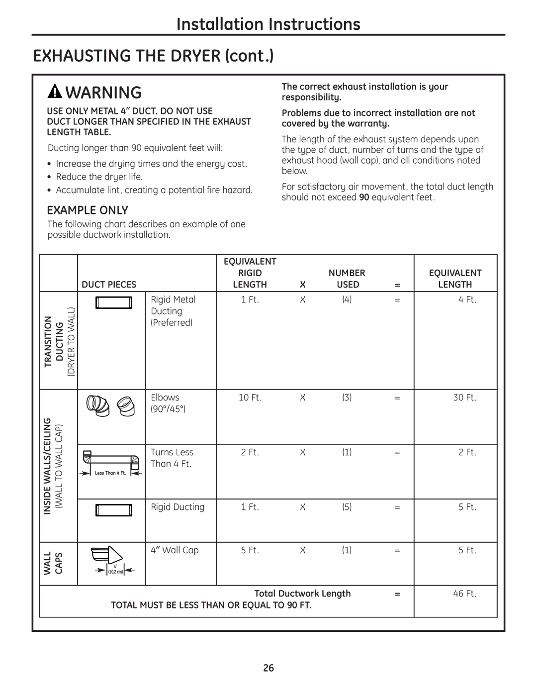
Installation Instructions Exhausting the Dryer
Example only
Rigid Metal Ducting ″ Wall Cap
Ducting Component Equivalency Chart
Turns less Than 4 Ft
Louvered Wall 10 Ft Cap ″ Wall Cap 23 Ft
Standard Rear Exhaust
Recommended Configuration to Minimize Exhaust Blockage
Using duct elbows will prevent duct kinking and collapsing
Dryer Exhaust to Side or Bottom of Cabinet
Level the Dryer
Plug in Dryer
Dryer Startup
Installation Instructions Final Setup
Press the Power button Dryer is now ready for use
Servicing
Remove Door
Remove Filler Plugs
Remove Handle
Reverse Door Catch
Reverse Handle
Installation Instructions Reversing the Door Swing
Install the handle on the opposite side of the door
Remove Hinges and Rehang Door
Following are normal sounds you may hear
Before you call for service…
Normal Operating Sounds
Warrantor General Electric Company. Louisville, KY
Operating Instructions Safety Instructions Installation
For The Period We Will Replace
What Is Not Covered in Canada
Warrantor Mabe Canada Inc Burlington, Ontario
Schedule Service
Consumer Support
Consommateur au Soutien
Ontario Burlington Inc Canada Mabe Garant
Installation Fonctionnement
GEsécheusevotredeGarantie
Page
Installation Mesures de sécurité Fonctionnement
’installation Instructions
Porte LA Remontez ET Charnières LES Enlevez
Remplissage DE Bouchons LES Enlevez
Poignée LA Enlevez
Porte LA DE Loquet LE Inversez
Entretoises deux les et poignée la tenant vis les Enlevez
Pas s’allumera ne
Installation/maintenance une
’emploi à prête maintenant est sécheuse La
Autres les et détachées pièces les Pour
Sécheuse LA Niveau DE Mettez
Blocage UN Minimiser Pour
Recommandée Configuration
’ÉVACUATION DE
Conduit de totale Longueur
Pi 4 m 1,2
Sont direction
PAS Faites NE
Nécessaires
De changements
’ÉVACUATION
Système DU Vérification DE Liste
Suite Sécheuse LA DE D’ALIMENTATION
Ouvert capot le pas laissez Ne Important
Pour blanc fil fils, 3 pour central fil neutre fil le
Terre LA À Mise DE Instructions
Haut en l’arrière à situé
Avec fermée boucle à ou fourchus Terminaux
Avertissement Sécurité Votre Pour
Avant constructions les pour fils
Minimum AWG #10 cuivre de Conducteur
Fuites DES Détection
GAZ À
Branchement DE Informations
Gaz de fuites de
Suite GAZ EN L’ALIMENTATION À Sécheuse LA DE Raccordement
Souple gaz de ligne la de raccord le Serrez
Commonwealth LE Dans
’ÉLÉVATION À DÛ Ajustement
Massachusetts DU
GAZ EN Alimentation
Nivellement de pattes les régler pour réglables Pinces
Équitablement
Répartis d’ouverture, carrés pouces
Sécheuse Votre DE Déballage
Encastrée Installation UNE Pour
Sécheuse LA DE Dimensions
QUE Autre Minimal Libre Espace
’incendie Risque
GAZ À Modèles LES Pour
Sécurité Votre Pour
Sécheuse la de nettoyage et Entretien
Tissu de d’entretien Étiquettes
Sécheuse la de utilisation et Chargement
De sécurité
Caractéristiques
Verrouillage Lock
Cycles mes Cycles My
Estimé restant temps Remaining Time Estimated
Défroisser Care Wrinkle
Alerte Signal
Wrinkle séchage Le .Care Wrinkle phase la
Ouverte est porte la
Convenance
Installation Fonctionnement Mesures de sécurité
Marche en mise Start
Électrique
Manuels Cycles
Capteur à Cycles
Sécheuse votre de contrôle de panneau Le
Sécurité Fonctionnement
Présence en appareil cet fonctionner faites vous
Appareil autre tout dans ou appareil cet dans
Ou avec sur, jouer pas laissez les Ne .d’enfants
Lorsque surveillance étroite une exercer faut Il
Installation Sécurité Fonctionnement
Instructions les suivez complets, détails des Pour
GAZ DE Odeur UNE Remarquez Vous SI
Pas n’utilisez ou pas N’entreposez
Série de et modèle de
Consommateur au Soutien
# Série
Numéros les ici Inscrivez