RM4 Control Interface (Optional )
![]() DANGER
DANGER ![]()
HAZARDOUS VOLTAGE
(Can Cause Severe Injury or Death)
Turn OFF all power before installation, adjustment, or removal of transfer switch or any of its components.
Optional Indicator LEDs
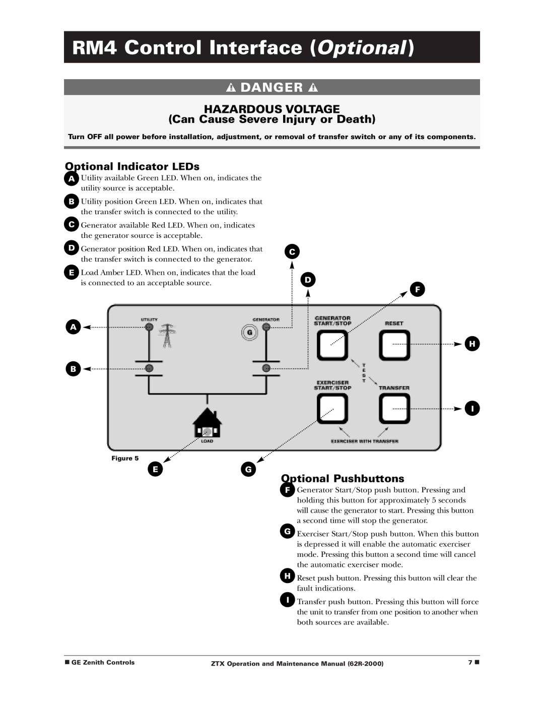
AUtility available Green LED. When on, indicates the utility source is acceptable.
BUtility position Green LED. When on, indicates that the transfer switch is connected to the utility.
CGenerator available Red LED. When on, indicates the generator source is acceptable.
DGenerator position Red LED. When on, indicates that the transfer switch is connected to the generator.
ELoad Amber LED. When on, indicates that the load is connected to an acceptable source.
A ![]()
![]()
B
Figure 5
EG
C
D
F
H
I
Optional Pushbuttons
F.F Generator Start/Stop push button. Pressing and holding this button for approximately 5 seconds will cause the generator to start. Pressing this button a second time will stop the generator.
G
G. Exerciser Start/Stop push button. When this button is depressed it will enable the automatic exerciser mode. Pressing this button a second time will cancel the automatic exerciser mode.
H
H. Reset push button. Pressing this button will clear the fault indications.
I.I Transfer push button. Pressing this button will force the unit to transfer from one position to another when both sources are available.
■ GE Zenith Controls | ZTX Operation and Maintenance Manual | 7 ■ |