Section 2 — Installation
Guardian
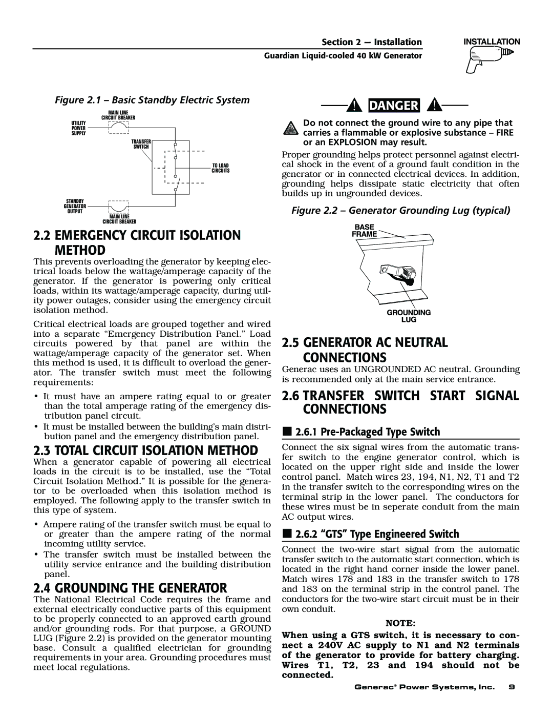
Figure 2.1 – Basic Standby Electric System | DANGER |
|
2.2 EMERGENCY CIRCUIT ISOLATION METHOD
This prevents overloading the generator by keeping elec- trical loads below the wattage/amperage capacity of the generator. If the generator is powering only critical loads, within its wattage/amperage capacity, during util- ity power outages, consider using the emergency circuit isolation method.
Critical electrical loads are grouped together and wired into a separate “Emergency Distribution Panel.” Load circuits powered by that panel are within the wattage/amperage capacity of the generator set. When this method is used, it is difficult to overload the gener- ator. The transfer switch must meet the following requirements:
•It must have an ampere rating equal to or greater than the total amperage rating of the emergency dis- tribution panel circuit.
•It must be installed between the building’s main distri- bution panel and the emergency distribution panel.
2.3 TOTAL CIRCUIT ISOLATION METHOD
When a generator capable of powering all electrical loads in the circuit is to be installed, use the “Total Circuit Isolation Method.” It is possible for the genera- tor to be overloaded when this isolation method is employed. The following apply to the transfer switch in this type of system.
•Ampere rating of the transfer switch must be equal to or greater than the ampere rating of the normal incoming utility service.
•The transfer switch must be installed between the utility service entrance and the building distribution panel.
2.4 GROUNDING THE GENERATOR
The National Electrical Code requires the frame and external electrically conductive parts of this equipment to be properly connected to an approved earth ground and/or grounding rods. For that purpose, a GROUND LUG (Figure 2.2) is provided on the generator mounting base. Consult a qualified electrician for grounding requirements in your area. Grounding procedures must meet local regulations.
Do not connect the ground wire to any pipe that carries a flammable or explosive substance – FIRE or an EXPLOSION may result.
Proper grounding helps protect personnel against electri- cal shock in the event of a ground fault condition in the generator or in connected electrical devices. In addition, grounding helps dissipate static electricity that often builds up in ungrounded devices.
Figure 2.2 – Generator Grounding Lug (typical)
2.5 GENERATOR AC NEUTRAL CONNECTIONS
Generac uses an UNGROUNDED AC neutral. Grounding is recommended only at the main service entrance.
2.6TRANSFER SWITCH START SIGNAL CONNECTIONS
 2.6.1
2.6.1 Pre-Packaged Type Switch
Connect the six signal wires from the automatic trans- fer switch to the engine generator control, which is located on the upper right side and inside the lower control panel. Match wires 23, 194, N1, N2, T1 and T2 in the transfer switch to the corresponding wires on the terminal strip in the lower panel. The conductors for these wires must be in seperate conduit from the main AC output wires.
 2.6.2 “GTS” Type Engineered Switch
Connect the
NOTE:
When using a GTS switch, it is necessary to con- nect a 240V AC supply to N1 and N2 terminals of the generator to provide for battery charging. Wires T1, T2, 23 and 194 should not be connected.
Generac® Power Systems, Inc. 9