Section 4 — Maintenance
Guardian
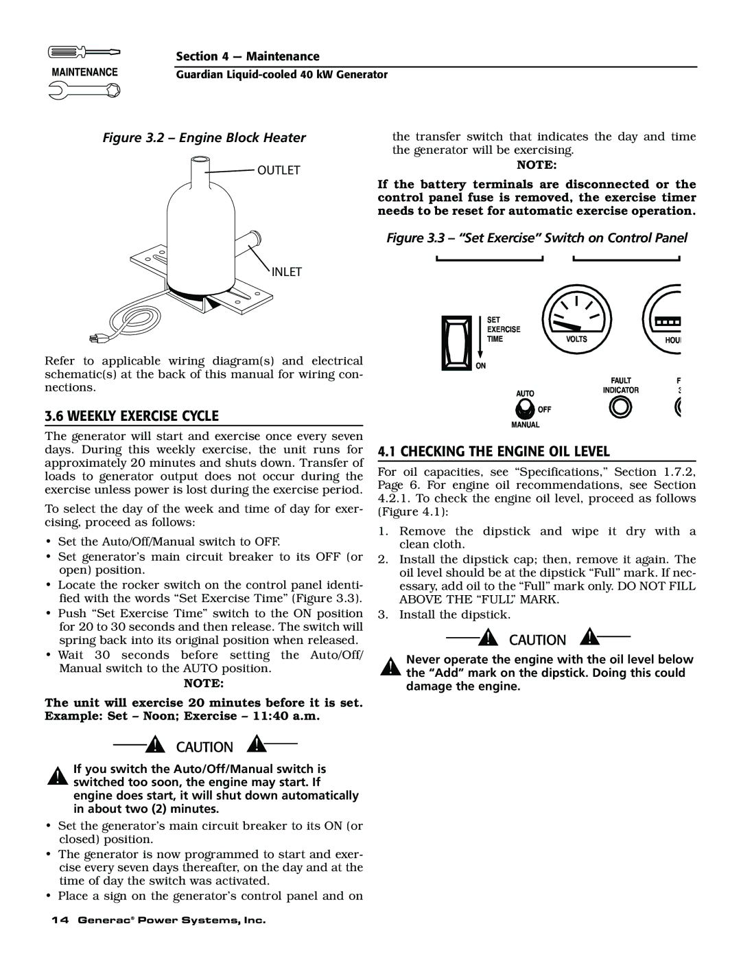
Figure 3.2 – Engine Block Heater | the transfer switch that indicates the day and time |
| the generator will be exercising. |
OUTLET
INLET
Refer to applicable wiring diagram(s) and electrical schematic(s) at the back of this manual for wiring con- nections.
3.6 WEEKLY EXERCISE CYCLE
The generator will start and exercise once every seven days. During this weekly exercise, the unit runs for approximately 20 minutes and shuts down. Transfer of loads to generator output does not occur during the exercise unless power is lost during the exercise period.
To select the day of the week and time of day for exer- cising, proceed as follows:
•Set the Auto/Off/Manual switch to OFF.
•Set generator’s main circuit breaker to its OFF (or open) position.
•Locate the rocker switch on the control panel identi- fied with the words “Set Exercise Time” (Figure 3.3).
•Push “Set Exercise Time” switch to the ON position for 20 to 30 seconds and then release. The switch will spring back into its original position when released.
•Wait 30 seconds before setting the Auto/Off/ Manual switch to the AUTO position.
NOTE:
The unit will exercise 20 minutes before it is set. Example: Set – Noon; Exercise – 11:40 a.m.
If you switch the Auto/Off/Manual switch is
!switched too soon, the engine may start. If engine does start, it will shut down automatically in about two (2) minutes.
•Set the generator’s main circuit breaker to its ON (or closed) position.
•The generator is now programmed to start and exer- cise every seven days thereafter, on the day and at the time of day the switch was activated.
•Place a sign on the generator’s control panel and on
NOTE:
If the battery terminals are disconnected or the control panel fuse is removed, the exercise timer needs to be reset for automatic exercise operation.
Figure 3.3 – “Set Exercise” Switch on Control Panel
4.1 CHECKING THE ENGINE OIL LEVEL
For oil capacities, see “Specifications,” Section 1.7.2, Page 6. For engine oil recommendations, see Section
4.2.1.To check the engine oil level, proceed as follows (Figure 4.1):
1.Remove the dipstick and wipe it dry with a clean cloth.
2.Install the dipstick cap; then, remove it again. The oil level should be at the dipstick “Full” mark. If nec- essary, add oil to the “Full” mark only. DO NOT FILL ABOVE THE “FULL” MARK.
3.Install the dipstick.
Never operate the engine with the oil level below
!the “Add” mark on the dipstick. Doing this could damage the engine.
14 Generac® Power Systems, Inc.