Section 2 — Installation
Guardian
2.8.1 PRIOR TO INITIAL START-UP
Prior to initially starting the generator, it must be
!properly prepared for use. Any attempt to crank or start the engine before it has been properly serviced with the recommended types and quanti- ties of engine fluids (oil, coolant, fuel, etc.) may result in an engine failure.
Before starting the generator for the first time, the installer must complete the following procedures. For
2.8.2 Transfer Switch
If this generator is used to supply power to any electri- cal system normally powered by an electric utility, the National Electrical Code requires that a transfer switch be installed. The transfer switch prevents electrical backfeed between two different electrical systems. (For additional information, see the applicable transfer switch manual for this unit.) The transfer switch, as well as the generator and other standby components, must be properly located and mounted in strict compli- ance with applicable codes, standards and regulations.
2.8.3 Fuel System
Make sure the fuel supply system to the generator (a) delivers the correct fuel at the correct pressure and (b) is properly purged and leak tested according to code. No fuel leakage is permitted. See “Specifications” (Page 6) for more information.
2.8.6 Belt Tension
Check the engine fan belt tension and condition prior to placing the unit into service and at recommended intervals. Belt tension is correct when a force of approx- imately 22 pounds (10 kg), applied midway between pulleys, deflects the belt about 3/8- to
2.8.7 Electrical System
Make sure the generator is properly connected to an approved earth ground and/or ground rod.
Make sure the generator battery is fully charged, proper- ly installed and interconnected, and ready for use.
Check to ensure that there are no loose electrical con- nections. Restrain any loose wires to keep them clear of any moving generator set components.
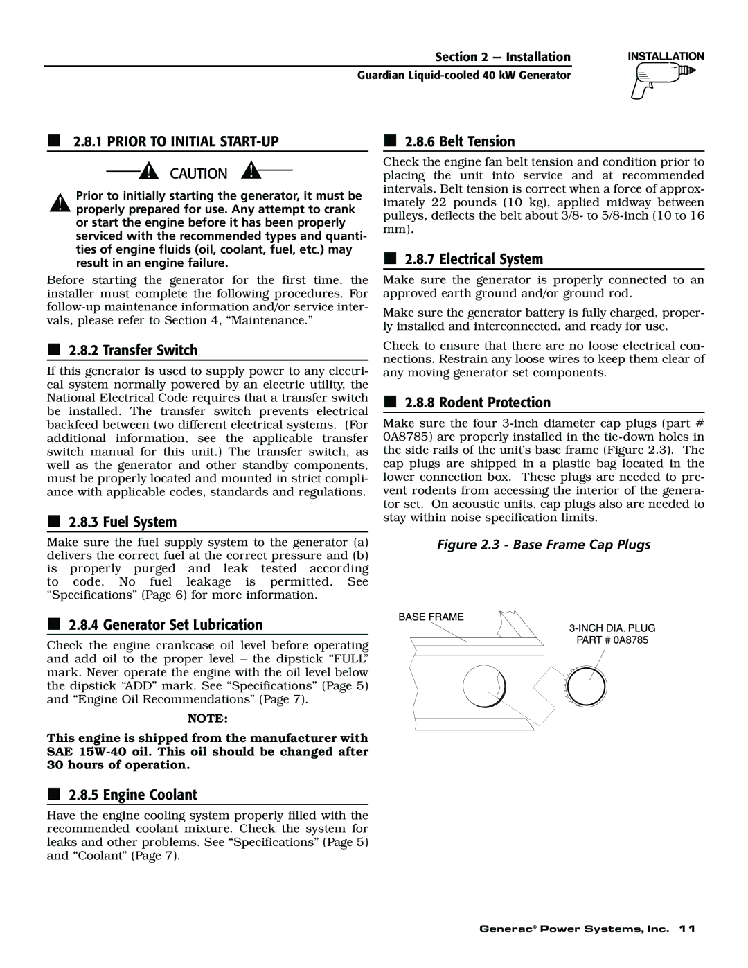
2.8.8 Rodent Protection
Make sure the four
Figure 2.3 - Base Frame Cap Plugs
2.8.4 Generator Set Lubrication
Check the engine crankcase oil level before operating and add oil to the proper level – the dipstick “FULL” mark. Never operate the engine with the oil level below the dipstick “ADD” mark. See “Specifications” (Page 5) and “Engine Oil Recommendations” (Page 7).
NOTE:
This engine is shipped from the manufacturer with SAE
2.8.5 Engine Coolant
Have the engine cooling system properly filled with the recommended coolant mixture. Check the system for leaks and other problems. See “Specifications” (Page 5) and “Coolant” (Page 7).
Generac® Power Systems, Inc. 11