Section 3 - Operation
Centurion
3.2.5 7.5 AMP IN-LINE FUSE
This
NOTE:
This fuse will not remove the positive (+) battery input power from the PCB when it opens. This means the exercise timer will not be reset. If this fuse does open, carefully check the wiring to the start, fuel, field boost and transfer outputs before replacing the fuse.
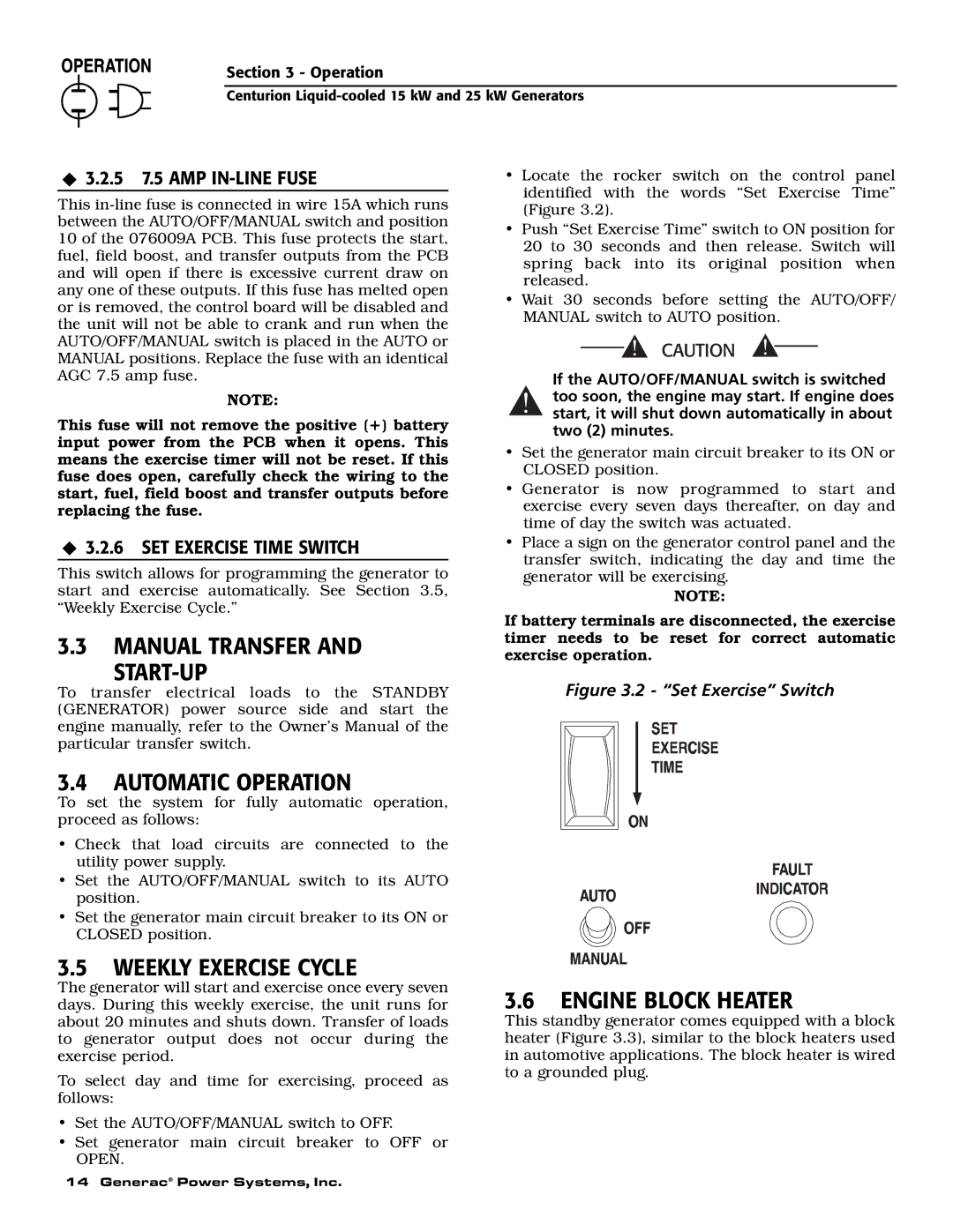
•Locate the rocker switch on the control panel identified with the words “Set Exercise Time” (Figure 3.2).
•Push “Set Exercise Time” switch to ON position for 20 to 30 seconds and then release. Switch will spring back into its original position when released.
•Wait 30 seconds before setting the AUTO/OFF/ MANUAL switch to AUTO position.
If the AUTO/OFF/MANUAL switch is switched
!too soon, the engine may start. If engine does start, it will shut down automatically in about two (2) minutes.
•Set the generator main circuit breaker to its ON or CLOSED position.
•Generator is now programmed to start and exercise every seven days thereafter, on day and time of day the switch was actuated.
3.2.6 SET EXERCISE TIME SWITCH
This switch allows for programming the generator to start and exercise automatically. See Section 3.5, “Weekly Exercise Cycle.”
3.3MANUAL TRANSFER AND
START-UP
To transfer electrical loads to the STANDBY (GENERATOR) power source side and start the engine manually, refer to the Owner’s Manual of the particular transfer switch.
3.4AUTOMATIC OPERATION
To set the system for fully automatic operation, proceed as follows:
•Check that load circuits are connected to the utility power supply.
•Set the AUTO/OFF/MANUAL switch to its AUTO position.
•Set the generator main circuit breaker to its ON or CLOSED position.
•Place a sign on the generator control panel and the transfer switch, indicating the day and time the generator will be exercising.
NOTE:
If battery terminals are disconnected, the exercise timer needs to be reset for correct automatic exercise operation.
Figure 3.2 - “Set Exercise” Switch
3.5WEEKLY EXERCISE CYCLE
The generator will start and exercise once every seven days. During this weekly exercise, the unit runs for about 20 minutes and shuts down. Transfer of loads to generator output does not occur during the exercise period.
To select day and time for exercising, proceed as follows:
•Set the AUTO/OFF/MANUAL switch to OFF.
•Set generator main circuit breaker to OFF or OPEN.
14 Generac® Power Systems, Inc.
3.6ENGINE BLOCK HEATER
This standby generator comes equipped with a block heater (Figure 3.3), similar to the block heaters used in automotive applications. The block heater is wired to a grounded plug.
