Section 4 — Maintenance
Centurion
1.The base frame of the unit contains an optional fuel inlet location that is capped at the factory. Check that it is secured in place. The same applies for any access ports in the roof of the enclosure. If any of these caps are missing, contact a Generac Authorized Dealer.
2.Inside the generator set, the chance of rodent entry into the control panel is greatly reduced by the inclusion of adjustable wire connectors. Check that the wire connector screws are tight, thus closing off any gap between the access holes and the wires.
4.7OUT OF SERVICE PROCEDURE
4.7.1 REMOVAL FROM SERVICE
If the generator cannot exercise every seven days, and it is to be out of service longer than 90 days, prepare the generator for storage as follows:
1.Start the engine and let it warm up.
2.Close the fuel shutoff valve in the fuel supply line and allow the unit to shut down.
3.Once the unit has shut down, it will signal a fault on the control panel.
4.Set the Auto/Off/Manual switch to OFF and turn off the utility power to the transfer switch.
5.While the engine is still warm from running, drain the oil completely. Refill the crankcase with SAE
6.Attach a tag to the engine indicating the viscosity and classification of the oil in the crankcase.
7.Remove the spark plug(s) and spray fogging agent into the spark plug(s) threaded openings. Reinstall and tighten the spark plug(s).
8.Remove the battery and store it in a cool, dry room on a wooden board. Never store the battery on any concrete or earthen floor.
9.Clean and wipe the entire generator.
4.7.2 RETURN TO SERVICE
To return the unit to service after storage, proceed as follows:
1.Verify that utility power is turned off to the transfer switch and that the Auto/Off/Manual switch is set to OFF.
2.Check the tag on the engine for oil viscosity and classification. Verify that the correct recom- mended oil is used in engine. See Section 1.14. If necessary, drain and refill with the proper oil.
3.Check the battery. Fill all cells to the proper level with deionized water. DO NOT USE TAP WATER IN THE BATTERY. Remove the battery before charging. Recharge the battery to 100 percent state of charge, or, if defective, replace the battery with a
4.Clean and wipe the entire generator.
5.Reconnect the battery. Observe battery polarity. Damage may occur if the battery is connected incorrectly.
6.Open the fuel shutoff valve.
7.Start the unit by moving the Auto/Off/Manual switch to MANUAL. Allow the unit to warm up thoroughly.
8.Stop the unit and set the Auto/Off/Manual switch to AUTO.
9.Turn on the utility power to the transfer switch.
10.The generator is now ready for service.
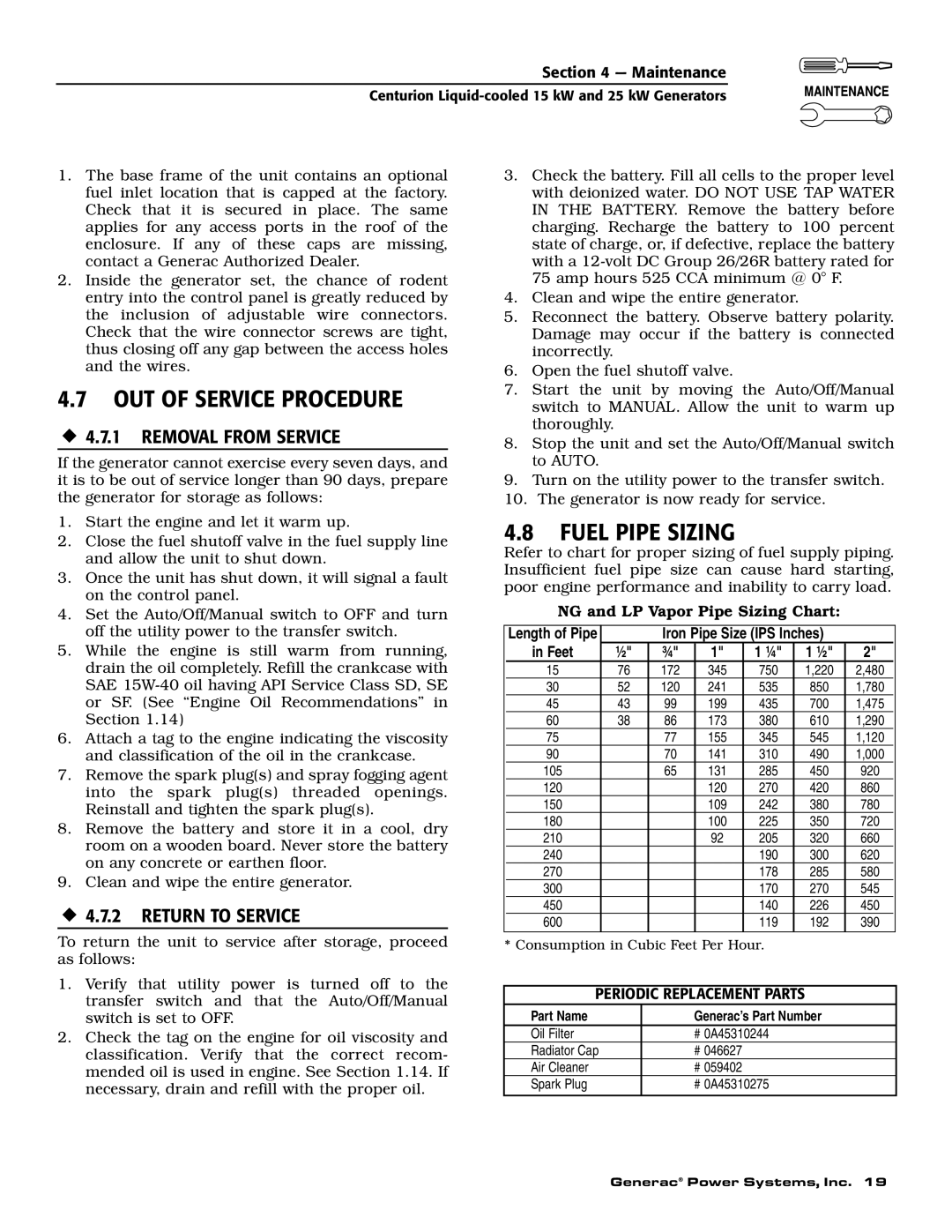
4.8FUEL PIPE SIZING
Refer to chart for proper sizing of fuel supply piping. Insufficient fuel pipe size can cause hard starting, poor engine performance and inability to carry load.
NG and LP Vapor Pipe Sizing Chart:
Length of Pipe |
|
| Iron Pipe Size (IPS Inches) |
|
| |||||
in Feet | ½" |
| ¾" |
| 1" | 1 ¼" |
| 1 ½" | 2" |
|
15 | 76 |
| 172 |
| 345 | 750 |
| 1,220 | 2,480 |
|
30 | 52 |
| 120 |
| 241 | 535 |
| 850 | 1,780 |
|
45 | 43 |
| 99 |
| 199 | 435 |
| 700 | 1,475 |
|
60 | 38 |
| 86 |
| 173 | 380 |
| 610 | 1,290 |
|
75 |
|
| 77 |
| 155 | 345 |
| 545 | 1,120 |
|
90 |
|
| 70 |
| 141 | 310 |
| 490 | 1,000 |
|
105 |
|
| 65 |
| 131 | 285 |
| 450 | 920 |
|
120 |
|
|
|
| 120 | 270 |
| 420 | 860 |
|
150 |
|
|
|
| 109 | 242 |
| 380 | 780 |
|
180 |
|
|
|
| 100 | 225 |
| 350 | 720 |
|
210 |
|
|
|
| 92 | 205 |
| 320 | 660 |
|
240 |
|
|
|
|
| 190 |
| 300 | 620 |
|
270 |
|
|
|
|
| 178 |
| 285 | 580 |
|
300 |
|
|
|
|
| 170 |
| 270 | 545 |
|
450 |
|
|
|
|
| 140 |
| 226 | 450 |
|
600 |
|
|
|
|
| 119 |
| 192 | 390 |
|
* Consumption in Cubic Feet Per Hour. |
|
|
| |||||||
|
|
|
|
| ||||||
PERIODIC REPLACEMENT PARTS |
|
|
| |||||||
Part Name |
|
|
| Generac’s Part Number |
|
| ||||
Oil Filter |
|
|
| # 0A45310244 |
|
|
| |||
Radiator Cap |
|
|
| # 046627 |
|
|
|
|
| |
Air Cleaner |
|
|
| # 059402 |
|
|
|
|
| |
Spark Plug |
|
|
| # 0A45310275 |
|
|
| |||
|
|
|
|
|
|
|
|
|
|
|
Generac® Power Systems, Inc. 19