Manuals
/
Generac
/
Lawn and Garden
/
Portable Generator
Generac
004912-0, 004912-1, 004913-0, 004913-1, 004913-2 owner manual Installation Diagram
Models:
004912-0, 004912-1, 004913-0, 004913-1, 004913-2
004912-0, 004912-1, 004913-0, 004913-1
1
27
52
52
Download
52 pages
6.08 Kb
24
25
26
27
28
29
30
31
<
>
Troubleshooting
Specification
Install
Wiring Diagram
4.6.4 BATTERY REPLACEMENT
Warranty
Maintenance
7 - Control Module Assembly
4.7OUT OF SERVICE PROCEDURE
3.2.3 FAULT INDICATOR LAMP
Page 27
Image 27
Section 7 - Installation Diagram
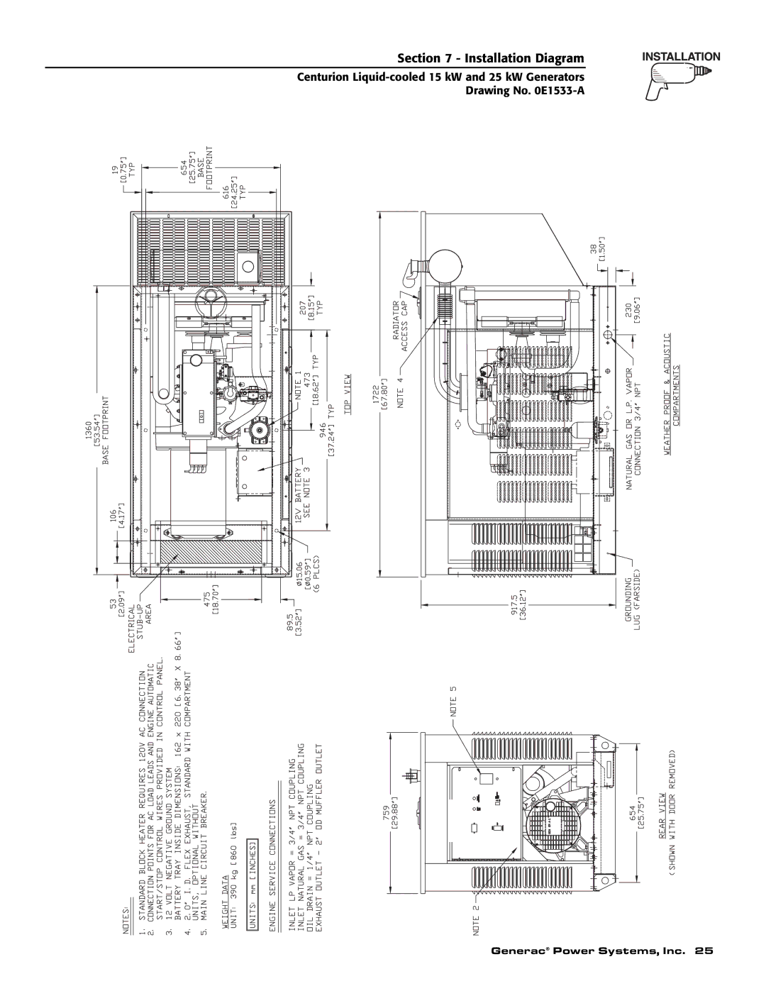
Centurion
Liquid-cooled
15 kW and 25 kW Generators
Drawing No.
0E1533-A
Generac
®
Power Systems, Inc. 25
Page 26
Page 28
Page 27
Image 27
Page 26
Page 28
Contents
Owner’s Manual
SHOULD ATTEMPT INSTALLATION
DEADLY EXHAUST FUMES. OUTDOOR INSTALLATION ONLY
CENTURION
INTRODUCTION
AUTHORIZED SERVICE DEALER LOCATION
OPERATION AND MAINTENANCE
HOW TO OBTAIN SERVICE
Inside Front Cover
Parts of the generator are rotating and/or hot
GENERAL HAZARDS
DANGER
Despite the safe design of this generator
Important Safety Instructions
ELECTRICAL HAZARDS
FIRE HAZARDS
EXPLOSION HAZARDS
1.4GENERATOR AC CONNECTION SYSTEMS
1.2TRANSFER SWITCH
1.1GENERATOR
1.3AUTOMATIC SYSTEM OPERATION
1.5 MAIN CIRCUIT BREAKER
1.7.1 LOW OIL PRESSURE SWITCH
1.7.2 HIGH COOLANT TEMPERATURE SWITCH
Figure 1.4 - Low Oil Pressure Switch
Figure 1.7 - Control Module Assembly
1.7.3 LOW COOLANT LEVEL SWITCH
1.8.1 UNPACKING PRECAUTIONS
Figure 1.5- High Coolant Temperature Switch
1.11 FUEL CONSUMPTION
1.10 SPECIFICATIONS
1.12RECONFIGURING THE FUEL SYSTEM
Figure 1.8 — Reconfigure the Fuel System
1.14 ENGINE OIL RECOMMENDATIONS
1.13 TORQUE SPECIFICATIONS
1.16 BEFORE INSTALLATION
2.1GENERATOR INSTALLATION
2.1.1 NFPA STANDARDS
2.2GENERATOR LOCATION
2.3GENERATOR MOUNTING AND SUPPORT
2.4BASIC STANDBY ELECTRIC SYSTEM
Figure 2.1 – Basic Standby Electric System
2.6TOTAL CIRCUIT ISOLATION METHOD
2.5EMERGENCY CIRCUIT ISOLATION METHOD
2.7GROUNDING THE GENERATOR
2.10.1 VENTED BATTERIES
2.9TRANSFER SWITCH START SIGNAL CONNECTIONS
2.10BATTERY INSTALLATION
2.8GENERATOR AC NEUTRAL CONNECTIONS
2.11.3 FUEL SYSTEM
2.11.2 TRANSFER SWITCH
2.11 PREPARATION BEFORE START-UP
2.11.1 PRIOR TO INITIAL START-UP
3.2CONTROL CONSOLE COMPONENTS
3.1USING A STANDARD “GTS” TRANSFER SWITCH
3.2.2 AUTO/OFF/MANUAL SWITCH
3.2.3 FAULT INDICATOR LAMP
3.4AUTOMATIC OPERATION
3.2.6 SET EXERCISE TIME SWITCH
Figure 3.2 - “Set Exercise” Switch
3.3MANUAL TRANSFER AND START-UP
4.4CHECKING FLUID LEVELS
4.2COOLING SYSTEM
4.3OVERLOAD PROTECTION FOR
ENGINE DC ELECTRICAL SYSTEM
DANGER
4.5MAINTENANCE OWNER/ OPERATOR CAN PERFORM
Figure 4.3 – Engine Air Cleaner
4.6MISCELLANEOUS MAINTENANCE
4.5.10 CHANGING THE ENGINE AIR CLEANER
4.6.1 CLEANING THE GENERATOR
4.6.5 RODENT PROTECTION
4.6.2 BATTERY
4.6.3 BATTERY MAINTENANCE
4.6.4 BATTERY REPLACEMENT
4.8FUEL PIPE SIZING
4.7OUT OF SERVICE PROCEDURE
4.7.1 REMOVAL FROM SERVICE
4.7.2 RETURN TO SERVICE
Service Maintenance Interval Information
4.9SCHEDULED MAINTENANCE
Level
Level
Maintenance
Level
Level
Maintenance
Level
Level
CORRECTION
5.1TROUBLESHOOTING POINTS
PROBLEM
CAUSE
24 Generac Power Systems, Inc
Section 6 — Notes
Centurion Liquid-cooled15 kW and 25 kW Generators
Drawing No. 0E1533-A
Section 7 - Installation Diagram
Generac Power Systems, Inc.
Centurion Liquid-cooled15 kW and 25 kW Generators
CenturionLiquid
Wiring Diagram
26 Generac Power Systems, Inc
Section
CONTROL
DC-VR
16DC-A
LOS DIS WLS FS
Section 8 - Electrical Data
28 Generac Power Systems, Inc
PREPACKAGE TRANSFER SWITCH CONNECTION TS3
LEGEND
Centurion Liquid-cooled15 kW and 25 kW Generators
LEGEND
Generac Power Systems, Inc.
Section 8 - Electrical Data
DESCRIPTION
Governor Assembly — Drawing No. 0E1331-B
ITEM
PART NO
Section 9 - Exploded Views and Parts
Centurion Liquid-cooled15 kW and 25 kW Generators
Mounting Base — Drawing No. 0E0768-B
1 11
0D8666
Section 9 - Exploded Views and Parts
PANEL FOR ACCESS COVER CABLE
Power Systems, Inc
NUT #037337
Section 9 - Exploded Views and Parts
Centurion Liquid-cooled25 kW Generator
Acoustic Compartment — Drawing No. 0E0772-G
Section 9 - Exploded Views and Parts
36 Generac Power Systems, Inc
0D9322
Section 9 - Exploded Views and Parts
38 Generac Power Systems, Inc
Section 9 - Exploded Views and Parts
Centurion Liquid-cooled15 kW and 25 kW Generators
Engine — Drawing No. 0E1228-E
17 4
11 12
16 7
14 12 24 19
Section 9 - Exploded Views and Parts
Centurion Liquid-cooled15 kW and 25 kW Generators
Radiator — Drawing No. 0E0769-H
3 11
29 40
9 14
6 6 43 10 D 40 41 11
Section 9 - Exploded Views and Parts
Centurion Liquid-cooled15 kW and 25 kW Generators
Fuel System — Drawing No. 0E0774-D
To Engine
Crankshaft
32 36 8
098671
8 STARTER SOLENOID
14 8 1 TO ENGINE BLOCK 16 5 6 7 9 15
Section 9 - Exploded Views and Parts
Centurion Liquid-cooled15 kW and 25 kW Generators
10 14 9
12 13 9 3 7 3 54 3 2
Section 9 - Exploded Views and Parts
CALIFORNIA EMISSION CONTROL WARRANTY STATEMENT
YOUR WARRANTY RIGHTS AND OBLIGATIONS
PURCHASER’S/OWNER’S WARRANTY RESPONSIBILITIES
1-800-333-1322
EMISSION CONTROL SYSTEM WARRANTY
EMISSION RELATED PARTS INCLUDE THE FOLLOWING
Section 10 – Warranty
GENERAC POWER SYSTEMS, INC
Section 10 – Warranty
WARRANTY SCHEDULE
THIS WARRANTY SHALL NOT APPLY TO THE FOLLOWING