General Information
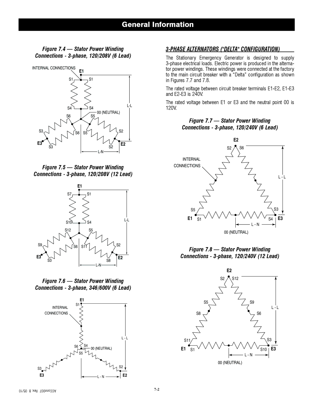
Figure 7.4 — Stator Power Winding
Connections - 3-phase, 120/208V (6 Lead)
INTERNAL CONNECTIONS
E1
S1S1
S4 | S4 | ||
00 (NEUTRAL) | |||
S6 | S5 | ||
|
S3 | S6 | S5 | S2 |
|
|
E3 | S2 | E2 |
S3 |
| |
|
|
Figure 7.5 — Stator Power Winding
Connections - 3-phase, 120/208V (12 Lead)
E1
S7S1
| S10 | S4 |
| |
|
|
| ||
| S12 | S5 |
|
|
S9 | S6 | S11 |
| S2 |
|
|
| ||
E3 | S3 |
| S8 | E2 |
|
|
| ||
|
|
|
|
Figure 7.6 — Stator Power Winding
Connections - 3-phase, 346/600V (6 Lead)
E1
S1 ![]()
INTERNAL
CONNECTIONS
|
| L - L |
S6 | S4 |
|
| 00 (NEUTRAL) |
|
| S5 |
|
S3 |
| S2 |
|
| |
E3 | L - N | E2 |
|
|
05/10 | B .Rev ACConn007 |
3-PHASE ALTERNATORS ("DELTA" CONFIGURATION)
The Stationary Emergency Generator is designed to supply
The rated voltage between circuit breaker terminals
The rated voltage between E1 or E3 and the neutral point 00 is 120V.
Figure 7.7 — Stator Power Winding
Connections - 3-phase, 120/240V (6 Lead)
E2
S2 S6
INTERNAL
CONNECTIONS
L - L
S5S3
E1 | S1 | S4 | E3 |
L - N
00 (NEUTRAL)
Figure 7.8 — Stator Power Winding
Connections - 3-phase, 120/240V (12 Lead)
| E2 |
S2 | S12 |
S5 | S9 |
| L - L |
S8 | S6 |
S11 |
| S3 | |
E1 | S1 | S10 | E3 |
|
| L - N |
|
|
| 00 (NEUTRAL) |
|