VHX SERIES STEAMER - ELECTRICAL OPERATION
ELECTRICAL OPERATION
WATER LEVEL CONTROLS
Low Level Cut-Off & Differential Control
The steamer is equipped with three water level sensing probes (high, low and low level
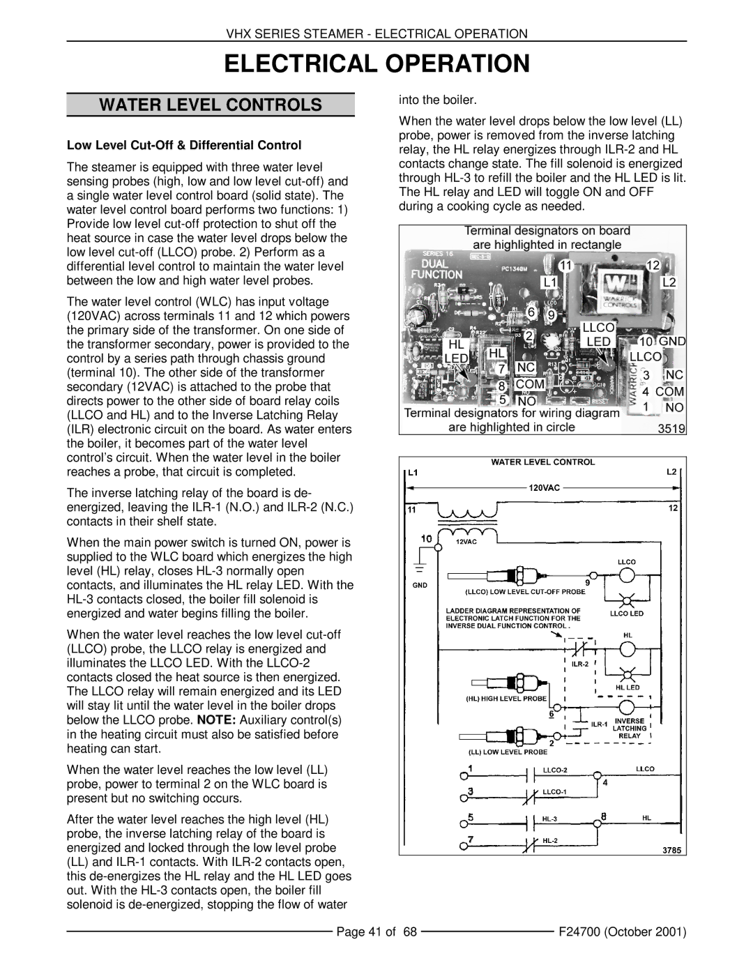
The water level control (WLC) has input voltage (120VAC) across terminals 11 and 12 which powers the primary side of the transformer. On one side of the transformer secondary, power is provided to the control by a series path through chassis ground (terminal 10). The other side of the transformer secondary (12VAC) is attached to the probe that directs power to the other side of board relay coils (LLCO and HL) and to the Inverse Latching Relay (ILR) electronic circuit on the board. As water enters the boiler, it becomes part of the water level control’s circuit. When the water level in the boiler reaches a probe, that circuit is completed.
The inverse latching relay of the board is de- energized, leaving the
When the main power switch is turned ON, power is supplied to the WLC board which energizes the high level (HL) relay, closes
When the water level reaches the low level
When the water level reaches the low level (LL) probe, power to terminal 2 on the WLC board is present but no switching occurs.
After the water level reaches the high level (HL) probe, the inverse latching relay of the board is energized and locked through the low level probe
(LL)and
into the boiler.
When the water level drops below the low level (LL) probe, power is removed from the inverse latching relay, the HL relay energizes through
Page 41 of 68 |
| F24700 (October 2001) |
|
