VHX SERIES STEAMER - SERVICE PROCEDURES AND ADJUSTMENTS
7.Once the correct pressure has been set, turn the gas supply and power switch OFF. Replace the adjustment screw cap and manifold pressure plug tap plug on the valve.
8.Turn the gas supply on and check for proper operation.
IGNITION CONTROL MODULE
CHECKS
1.Turn the power switch ON and allow the boiler to fill.
2.Aux. water level control satisfied and high limit closed.
3.Press the reset switch.
A.Combustion blower comes on and generates pressure to close the air pressure switch contacts.
B.Ignition control module is energized and trial for ignition starts. Check for 24VAC between terminals five and six.
C.Ignition module closes the internal pilot valve contacts. Check for 24 volts between terminals two and three.
1)High voltage is sent from terminal nine to the spark electrode and sparking begins.
2)At the same time, pilot timing circuit (control board) and pilot valve are both energized allowing gas flow to the pilot.
NOTE: The pilot valve will be energized by the relay board timer circuit for approximately 15 seconds to light the main burner.
D.Pilot ignition is established (pilot lit), and main gas valve is energized. Check for 24 volts between terminals one and two.
1)Sparking stops.
2)Ignition module monitors main burner flame.
3)After 15 seconds relay board timer times out.
a. Pilot valve
E.As long as the ignition control module is sensing a burner flame through the ignition cable on terminal nine, the internal main voltage (MV) and pilot (PV) contacts (N.O.) remain closed.
NOTE: If pilot flame is not sensed within 15 seconds, you can
F."Rapidly", turn the power switch OFF then ON. A rapid switching is needed to keep the boiler from starting automatic blowdown. Then press the reset button.
NOTE: If the power is not
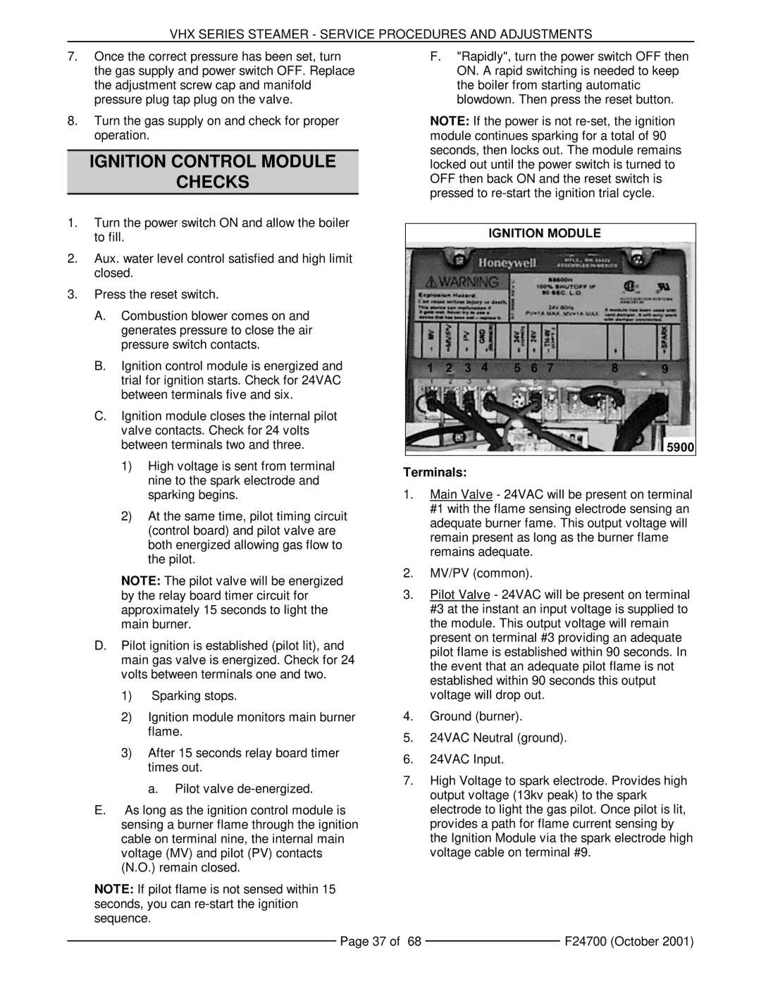
Terminals:
1.Main Valve - 24VAC will be present on terminal #1 with the flame sensing electrode sensing an adequate burner fame. This output voltage will remain present as long as the burner flame remains adequate.
2.MV/PV (common).
3.Pilot Valve - 24VAC will be present on terminal #3 at the instant an input voltage is supplied to the module. This output voltage will remain present on terminal #3 providing an adequate pilot flame is established within 90 seconds. In the event that an adequate pilot flame is not established within 90 seconds this output voltage will drop out.
4.Ground (burner).
5.24VAC Neutral (ground).
6.24VAC Input.
7.High Voltage to spark electrode. Provides high output voltage (13kv peak) to the spark electrode to light the gas pilot. Once pilot is lit, provides a path for flame current sensing by the Ignition Module via the spark electrode high voltage cable on terminal #9.
Page 37 of 68 |
| F24700 (October 2001) |
|