VHX SERIES STEAMERS - REMOVAL AND REPLACEMENT OF PARTS
BURNER HEAD ASSEMBLY
WARNING: DISCONNECT THE ELECTRICAL POWER TO THE MACHINE AT THE MAIN CIRCUIT BOX. PLACE A TAG ON THE CIRCUIT BOX INDICATING THE CIRCUIT IS BEING SERVICED.
WARNING: SHUT OFF THE GAS SUPPLY BEFORE SERVICING THE UNIT.
1.Remove the pressure gauge tubing and power cable from the rear of the control panel then remove the panel.
2.Disconnect the spark ignition cable from the ignitor terminal.
3.Disconnect pilot gas tubing from the air pressure switch tee.
4.Separate the union above the main gas valve and remove the gas valve piping assembly.
NOTE: Removal of the gas valve piping assembly assumes the use of a gas line quick connect or union at the gas supply inlet to the steamer.
5.Remove the screws from the burner head assembly end plate and pull the assembly out from the complete burner assembly.
6.Reverse procedure to install and check for proper operation.
COMPLETE BURNER
ASSEMBLY
WARNING: DISCONNECT THE ELECTRICAL POWER TO THE MACHINE AT THE MAIN CIRCUIT BOX. PLACE A TAG ON THE CIRCUIT BOX INDICATING THE CIRCUIT IS BEING SERVICED.
WARNING: SHUT OFF THE GAS SUPPLY BEFORE SERVICING THE UNIT.
1.Refer to steps 1 through 4 under "BURNER HEAD ASSEMBLY".
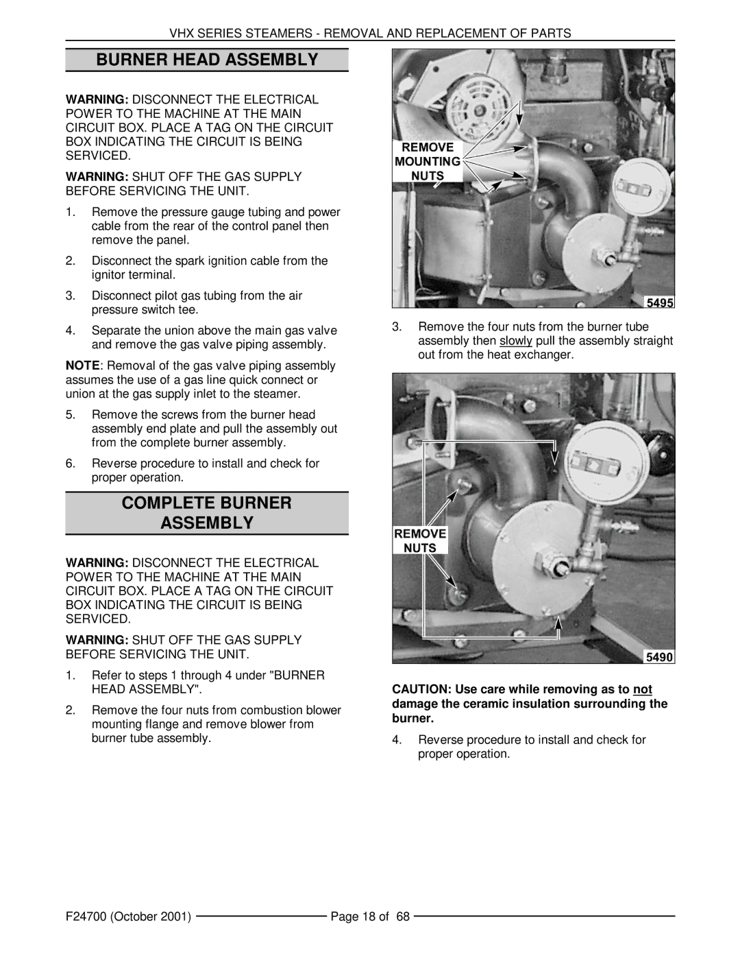
2.Remove the four nuts from combustion blower mounting flange and remove blower from burner tube assembly.
3.Remove the four nuts from the burner tube assembly then slowly pull the assembly straight out from the heat exchanger.
CAUTION: Use care while removing as to not damage the ceramic insulation surrounding the burner.
4.Reverse procedure to install and check for proper operation.
F24700 (October 2001) |
| Page 18 of 68 |
|