VHX SERIES STEAMERS - REMOVAL AND REPLACEMENT OF PARTS
HEAT EXCHANGER
WARNING: SHUT OFF THE GAS BEFORE SERVICING THE UNIT.
WARNING: ALL GAS JOINTS DISTURBED DURING SERVICING MUST BE CHECKED FOR LEAKS. CHECK WITH A SOAP AND WATER SOLUTION (BUBBLES). DO NOT USE AN OPEN FLAME.
1.Blowdown the boiler and, if necessary, allow to cool.
2.Disconnect the electrical power to the machine at the main circuit box. Place a tag on the circuit box indicating the circuit is being serviced.
3.Remove the pressure gauge tubing and power cable from the rear of the control panel then remove the panel.
4.Disconnect the electrical lead wires exiting the boiler control box from:
A.Auxiliary LLCO probe (Orange).
B.Burner ground (green).
C.Air pressure switch (yellow & yellow/white stripe).
D.Main gas valve (purple & grey).
E.Pilot burner valve (red & grey).
F.Spark ignition cable.
5.Remove bolts securing the boiler control box (front) to the base frame.
A.Lift up on left side of box and slide out.
6.Disconnect pilot gas tubing from the air pressure switch tee.
7.Separate the union above the main gas valve and remove the gas valve piping assembly.
NOTE: Removal of the gas valve piping assembly assumes the use of a gas line quick connect or union at the gas supply inlet to the steamer.
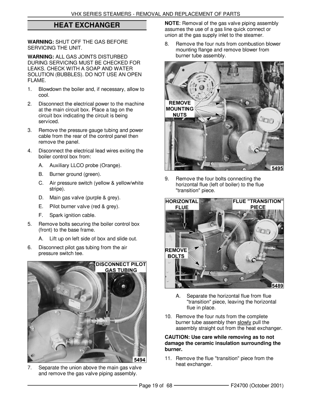
8.Remove the four nuts from combustion blower mounting flange and remove blower from burner tube assembly.
9.Remove the four bolts connecting the horizontal flue (left of boiler) to the flue "transition" piece.
A.Separate the horizontal flue from flue "transition" piece, leaving the horizontal flue in place.
10.Remove the four nuts from the complete burner tube assembly then slowly pull the assembly straight out from the heat exchanger.
CAUTION: Use care while removing as to not damage the ceramic insulation surrounding the burner.
11.Remove the flue "transition" piece from the heat exchanger.
Page 19 of 68 |
| F24700 (October 2001) |
|