VHX SERIES STEAMER - ELECTRICAL OPERATION
RELAY BOARD
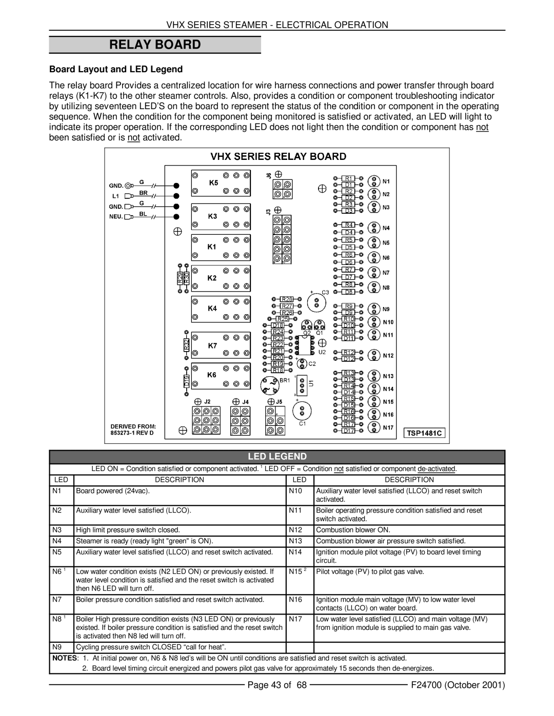
Board Layout and LED Legend
The relay board Provides a centralized location for wire harness connections and power transfer through board relays
LED LEGEND
LED ON = Condition satisfied or component activated. 1 LED OFF = Condition not satisfied or component
LED | DESCRIPTION | LED | DESCRIPTION |
|
|
|
|
N1 | Board powered (24vac). | N10 | Auxiliary water level satisfied (LLCO) and reset switch |
|
|
| activated. |
|
|
|
|
N2 | Auxiliary water level satisfied (LLCO). | N11 | Boiler operating pressure condition satisfied and reset |
|
|
| switch activated. |
|
|
|
|
N3 | High limit pressure switch closed. | N12 | Combustion blower ON. |
|
|
|
|
N4 | Steamer is ready (ready light "green" is ON). | N13 | Combustion blower air pressure switch satisfied. |
|
|
|
|
N5 | Auxiliary water level satisfied (LLCO) and reset switch activated. | N14 | Ignition module pilot voltage (PV) to board level timing |
|
|
| circuit. |
|
|
|
|
N6 1 | Low water condition exists (N2 LED ON) or previously existed. If | N15 2 | Pilot voltage (PV) to pilot gas valve. |
| water level condition is satisfied and the reset switch is activated |
|
|
| then N6 LED will turn off. |
|
|
|
|
|
|
N7 | Boiler pressure condition satisfied and reset switch activated. | N16 | Ignition module main voltage (MV) to low water level |
|
|
| contacts (LLCO) on water board. |
|
|
|
|
N8 1 | Boiler High pressure condition exists (N3 LED ON) or previously | N17 | Low water level satisfied (LLCO) and main voltage (MV) |
| existed. If boiler pressure condition is satisfied and the reset switch |
| from ignition module is supplied to main gas valve. |
| is activated then N8 led will turn off. |
|
|
|
|
|
|
N9 | Cycling pressure switch CLOSED “call for heat”. |
|
|
|
|
|
|
NOTES: 1. At initial power on, N6 & N8 led’s will be ON until conditions are satisfied and reset switch is activated.
2. Board level timing circuit energized and powers pilot gas valve for approximately 15 seconds then
Page 43 of 68 |
| F24700 (October 2001) |
|