VHX SERIES STEAMERS - REMOVAL AND REPLACEMENT OF PARTS
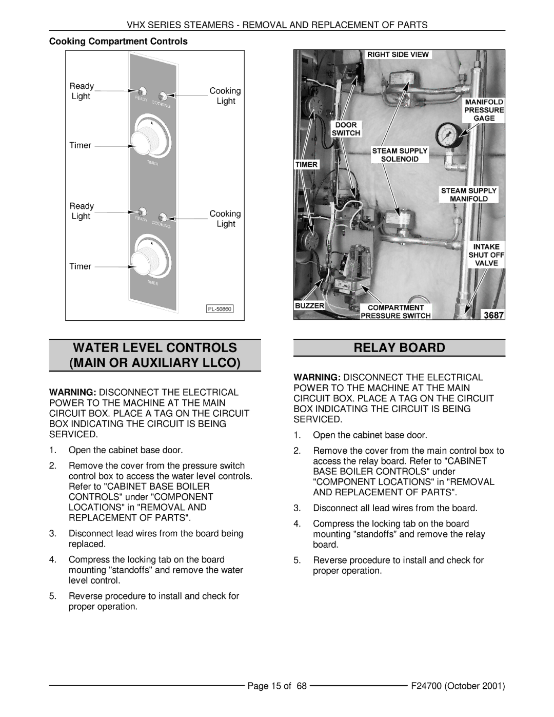
Cooking Compartment Controls
WATER LEVEL CONTROLS (MAIN OR AUXILIARY LLCO)
WARNING: DISCONNECT THE ELECTRICAL POWER TO THE MACHINE AT THE MAIN CIRCUIT BOX. PLACE A TAG ON THE CIRCUIT BOX INDICATING THE CIRCUIT IS BEING SERVICED.
1.Open the cabinet base door.
2.Remove the cover from the pressure switch control box to access the water level controls. Refer to "CABINET BASE BOILER CONTROLS" under "COMPONENT LOCATIONS" in "REMOVAL AND REPLACEMENT OF PARTS".
3.Disconnect lead wires from the board being replaced.
4.Compress the locking tab on the board mounting "standoffs" and remove the water level control.
5.Reverse procedure to install and check for proper operation.
RELAY BOARD
WARNING: DISCONNECT THE ELECTRICAL POWER TO THE MACHINE AT THE MAIN CIRCUIT BOX. PLACE A TAG ON THE CIRCUIT BOX INDICATING THE CIRCUIT IS BEING SERVICED.
1.Open the cabinet base door.
2.Remove the cover from the main control box to access the relay board. Refer to "CABINET BASE BOILER CONTROLS" under "COMPONENT LOCATIONS" in "REMOVAL AND REPLACEMENT OF PARTS".
3.Disconnect all lead wires from the board.
4.Compress the locking tab on the board mounting "standoffs" and remove the relay board.
5.Reverse procedure to install and check for proper operation.
Page 15 of 68 |
| F24700 (October 2001) |
|
