Section 3 — Operation

Guardian Liquid-cooled 40 kW Generator

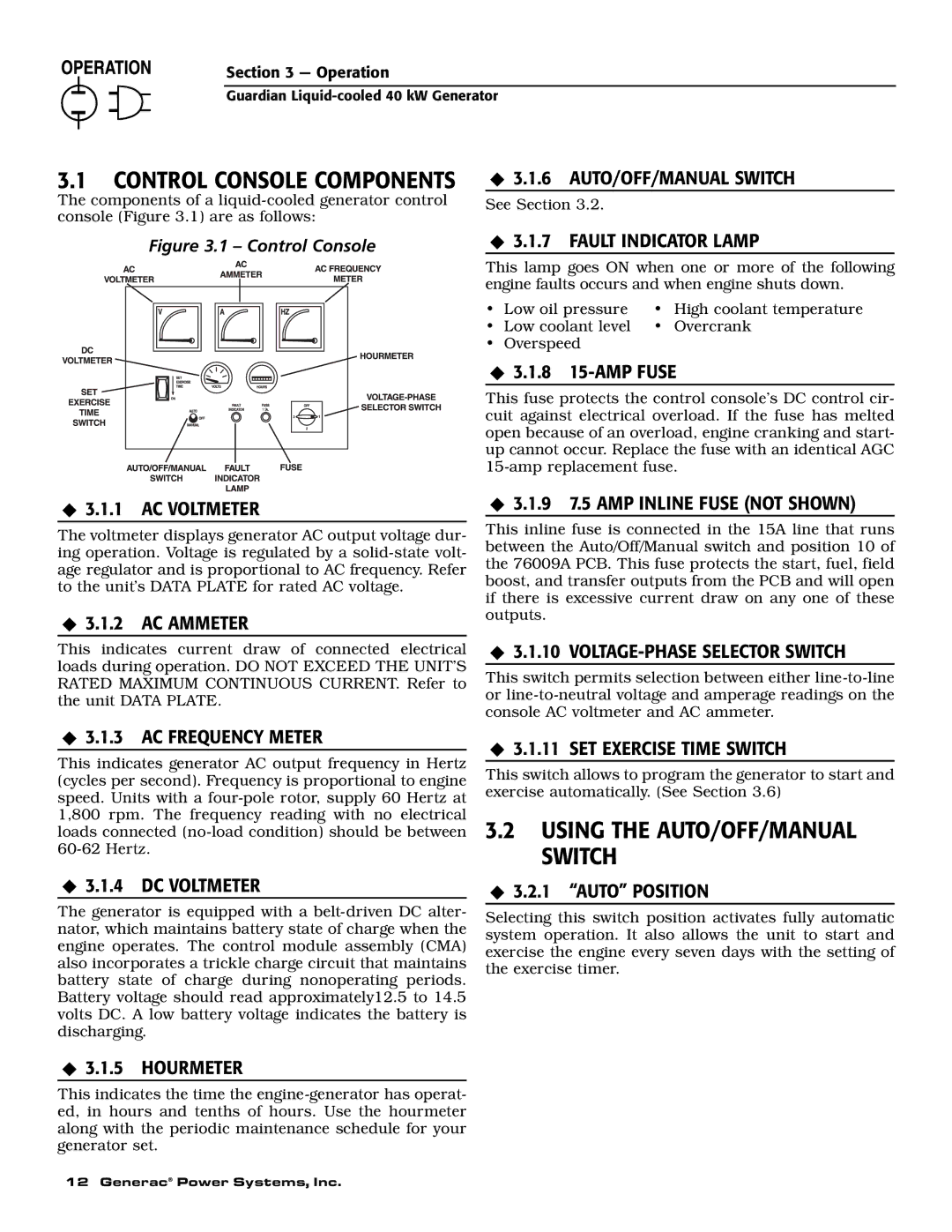
3.1 CONTROL CONSOLE COMPONENTS

‹ 3.1.6 AUTO/OFF/MANUAL SWITCH

The components of a liquid-cooled generator control

See Section 3.2.

console (Figure 3.1) are as follows:


Figure 3.1 – Control Console

15

‹3.1.7 FAULT INDICATOR LAMP

This lamp goes ON when one or more of the following engine faults occurs and when engine shuts down.

Low oil pressure

High coolant temperature

Low coolant level

Overcrank

Overspeed

‹3.1.8 15-AMP FUSE

This fuse protects the control console’s DC control cir- cuit against electrical overload. If the fuse has melted open because of an overload, engine cranking and start- up cannot occur. Replace the fuse with an identical AGC 15-amp replacement fuse.

‹3.1.1 AC VOLTMETER

The voltmeter displays generator AC output voltage dur- ing operation. Voltage is regulated by a solid-state volt- age regulator and is proportional to AC frequency. Refer to the unit’s DATA PLATE for rated AC voltage.

‹3.1.2 AC AMMETER

This indicates current draw of connected electrical loads during operation. DO NOT EXCEED THE UNIT’S RATED MAXIMUM CONTINUOUS CURRENT. Refer to the unit DATA PLATE.

‹3.1.3 AC FREQUENCY METER

This indicates generator AC output frequency in Hertz (cycles per second). Frequency is proportional to engine speed. Units with a four-pole rotor, supply 60 Hertz at 1,800 rpm. The frequency reading with no electrical loads connected (no-load condition) should be between 60-62 Hertz.

‹3.1.4 DC VOLTMETER

The generator is equipped with a belt-driven DC alter- nator, which maintains battery state of charge when the engine operates. The control module assembly (CMA) also incorporates a trickle charge circuit that maintains battery state of charge during nonoperating periods. Battery voltage should read approximately12.5 to 14.5 volts DC. A low battery voltage indicates the battery is discharging.

‹3.1.9 7.5 AMP INLINE FUSE (NOT SHOWN)

This inline fuse is connected in the 15A line that runs between the Auto/Off/Manual switch and position 10 of the 76009A PCB. This fuse protects the start, fuel, field boost, and transfer outputs from the PCB and will open if there is excessive current draw on any one of these outputs.

‹3.1.10 VOLTAGE-PHASE SELECTOR SWITCH

This switch permits selection between either line-to-line or line-to-neutral voltage and amperage readings on the console AC voltmeter and AC ammeter.

‹3.1.11 SET EXERCISE TIME SWITCH

This switch allows to program the generator to start and exercise automatically. (See Section 3.6)

3.2USING THE AUTO/OFF/MANUAL SWITCH

‹3.2.1 “AUTO” POSITION

Selecting this switch position activates fully automatic system operation. It also allows the unit to start and exercise the engine every seven days with the setting of the exercise timer.

‹3.1.5 HOURMETER

This indicates the time the engine-generator has operat- ed, in hours and tenths of hours. Use the hourmeter along with the periodic maintenance schedule for your generator set.

12 Generac® Power Systems, Inc.

Page 14
Image 14
Generac Power Systems 0046263, 0043733, 0046264, 0046262, 0043734, 0043735 owner manual Using the AUTO/OFF/MANUAL Switch

0043735, 0043734, 0046262, 0046263, 0046264 specifications

Generac Power Systems has established itself as a leader in the power generation industry, best known for its wide range of products designed for various power needs. Among its offerings are model numbers 0043733, 0046264, 0046263, 0046262, and 0043734. Each unit reflects Generac's commitment to innovation, reliability, and efficiency in providing backup power solutions.

The Generac model 0043733 is a powerful portable generator known for its robust performance and user-friendly design. It typically features a high starting wattage, capable of powering essential appliances during outages. With a compact design and ergonomic handle, it ensures easy transportability, making it an excellent choice for outdoor activities or emergency backup. This model often incorporates advanced technology such as digital watt meters for real-time monitoring and fuel level indicators to enhance user convenience.

Moving on to model 0046264, this unit is engineered for reliability in home standby applications. Its automatic transfer switch allows for seamless switching from grid power to generator power in the event of an outage. This ensures a continuous power supply without any manual intervention. Generac's Quiet-Test technology makes this model exceptionally quiet, operating at a lower decibel level compared to traditional generators, enhancing its suitability for residential areas.

The 0046263 model is similar to the 0046264 but is designed for slightly different power requirements and configurations. It offers a range of customizable options, allowing users to tailor the system to their specific needs. Advanced monitoring capabilities often come standard, enabling users to track performance and receive alerts via smartphone or other devices.

Model 0046262 is also tailored for homeowners, focusing on versatility and efficiency. It usually features a highly efficient engine, capable of providing substantial power while optimizing fuel consumption. Its sturdy build ensures durability, making it suitable for various weather conditions.

Lastly, the 0043734 model is designed for commercial use, capable of handling larger power needs. It typically comes equipped with technologies such as remote monitoring and diagnostics, making it easier to maintain and service. With a heavy-duty construction, this model is built to withstand demanding environments while providing reliable, uninterrupted power.

In summary, Generac Power Systems offers a diverse range of backup power solutions through models such as 0043733, 0046264, 0046263, 0046262, and 0043734. With features focusing on portability, reliability, efficiency, and advanced technology, these models cater to various power requirements, ensuring customers can find the ideal generator for their needs.