INSTALLATION
SETTING THE SWITCHES FOR THE
TWO VOLTAGE SELECTOR SWITCHES
(Not available on U.S. and Canadian models)
CHANNEL STEP/FM
Only
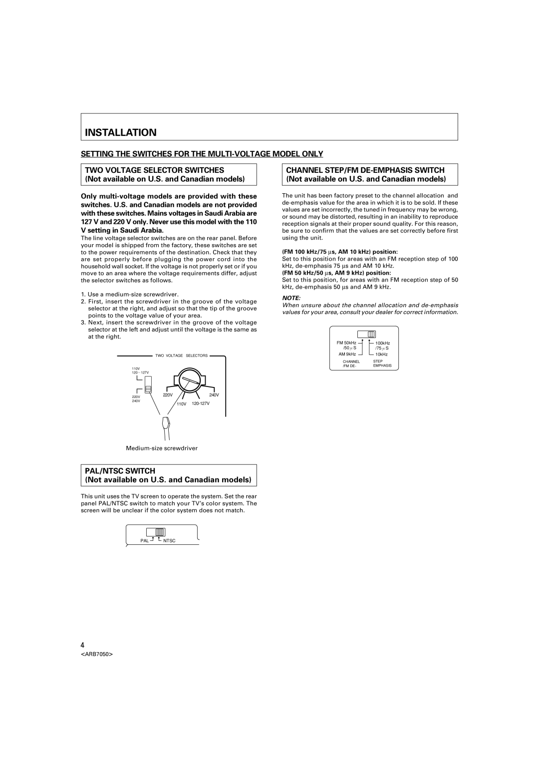
The line voltage selector switches are on the rear panel. Before your model is shipped from the factory, these switches are set to the power requirements of the destination. Check that they are set properly before plugging the power cord into the household wall socket. If the voltage is not properly set or if you move to an area where the voltage requirements differ, adjust the selector switches as follows.
1.Use a
2.First, insert the screwdriver in the groove of the voltage selector at the right, and adjust so that the tip of the groove points to the voltage value of your area.
3.Next, insert the screwdriver in the groove of the voltage selector at the left and adjust until the voltage is the same as at the right.
TWO VOLTAGE SELECTORS
110V
120~127V
220V | 220V | 240V |
240V | 110V | |
|
PAL/NTSC SWITCH
(Not available on U.S. and Canadian models)
This unit uses the TV screen to operate the system. Set the rear panel PAL/NTSC switch to match your TV’s color system. The screen will be unclear if the color system does not match.
The unit has been factory preset to the channel allocation and
(FM 100 kHz/75 ∝s, AM 10 kHz) position:
Set to this position for areas with an FM reception step of 100 kHz,
(FM 50 kHz/50 ∝s, AM 9 kHz) position:
Set to this position, for areas with an FM reception step of 50 kHz,
NOTE:
When unsure about the channel allocation and
FM 50kHz | 100kHz |
/50μS | /75μS |
AM 9kHz | 10kHz |
CHANNEL | STEP |
/FM DE- | EMPHASIS |
PAL | NTSC |
4
<ARB7050>
