CONNECTIONS
ANTENNA CONNECTIONS
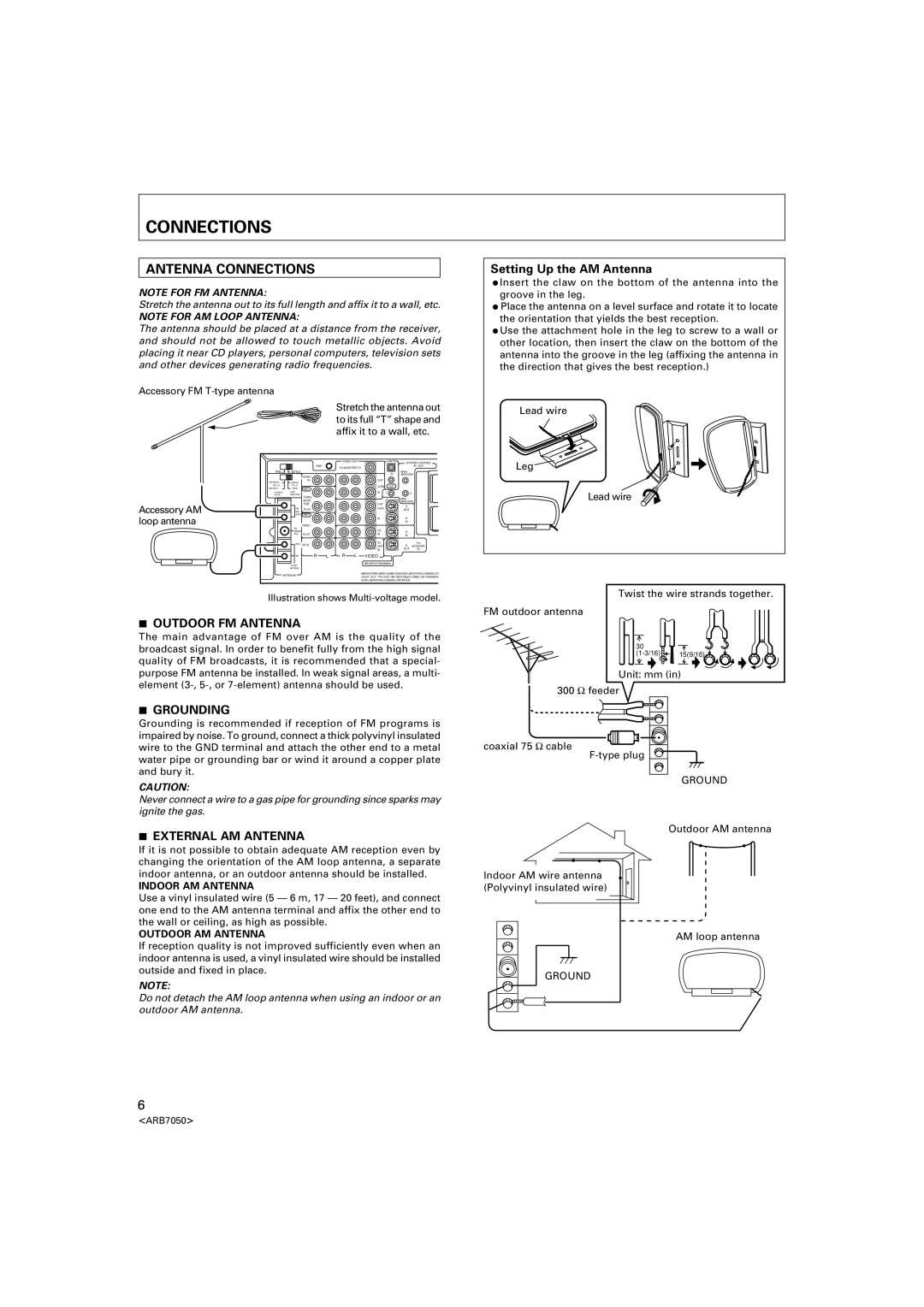
NOTE FOR FM ANTENNA:
Stretch the antenna out to its full length and affix it to a wall, etc.
NOTE FOR AM LOOP ANTENNA:
The antenna should be placed at a distance from the receiver, and should not be allowed to touch metallic objects. Avoid placing it near CD players, personal computers, television sets and other devices generating radio frequencies.
Accessory FM
Stretch the antenna out to its full “T” shape and affix it to a wall, etc.
Setting Up the AM Antenna
÷Insert the claw on the bottom of the antenna into the groove in the leg.
÷Place the antenna on a level surface and rotate it to locate the orientation that yields the best reception.
÷Use the attachment hole in the leg to screw to a wall or other location, then insert the claw on the bottom of the antenna into the groove in the leg (affixing the antenna in the direction that gives the best reception.)
Lead wire
Accessory AM loop antenna
PAL ![]()
FM 50kHz /50μS
AM 9kHz
CHANNEL /FM DE-
GND
 NTSC
NTSC
PHONO
IN
100kHz /75μS
10kHz REC STEP
EMPHASIS
TAPE2
MONI-
TOR
FM PLAY
BAL
300Ω REC
TAPE1
FM
UNBAL
75Ω PLAY
GND CD IN
AM | R | L |
LOOP
ANTENA
VIDEO OUT | CONTROL | SYSTEM CONTROL | |
|
| ||
TO MONITOR TV |
|
| IR OUT |
|
|
| |
| IN | MAIN- |
|
| REPEATER | ||
OUT |
|
|
|
VCR2 | OUT |
|
|
IN 1 |
|
| 2 |
|
| MINI- |
|
OUT |
| REPEATER | |
| S |
| |
VCR1 |
|
| |
| OUT |
| |
IN |
| S |
|
|
| IN |
|
LD |
| S |
|
IN |
| IN |
|
TV |
| S | TO |
/SAT |
| MONITOR | |
IN |
| OUT | TV |
R L VIDEO
SEE INSTRUCTION MANUAL
Leg
Lead wire
ANTENNA
MANUFACTURED UNDER LICENSE FROM DOLBY LABORATORIES LICENSING CORPORATION.
Illustration shows
7OUTDOOR FM ANTENNA
The main advantage of FM over AM is the quality of the broadcast signal. In order to benefit fully from the high signal quality of FM broadcasts, it is recommended that a special- purpose FM antenna be installed. In weak signal areas, a multi- element
7GROUNDING
Grounding is recommended if reception of FM programs is impaired by noise. To ground, connect a thick polyvinyl insulated wire to the GND terminal and attach the other end to a metal water pipe or grounding bar or wind it around a copper plate and bury it.
CAUTION:
Never connect a wire to a gas pipe for grounding since sparks may ignite the gas.
7EXTERNAL AM ANTENNA
If it is not possible to obtain adequate AM reception even by changing the orientation of the AM loop antenna, a separate indoor antenna, or an outdoor antenna should be installed.
INDOOR AM ANTENNA
Use a vinyl insulated wire (5 — 6 m, 17 — 20 feet), and connect one end to the AM antenna terminal and affix the other end to the wall or ceiling, as high as possible.
OUTDOOR AM ANTENNA
If reception quality is not improved sufficiently even when an indoor antenna is used, a vinyl insulated wire should be installed outside and fixed in place.
NOTE:
Do not detach the AM loop antenna when using an indoor or an outdoor AM antenna.
Twist the wire strands together.
FM outdoor antenna
30 |
|
15(9/16) |
Unit: mm (in)
300 Ω feeder
coaxial 75 Ω cable
GROUND
Outdoor AM antenna
Indoor AM wire antenna (Polyvinyl insulated wire)
AM loop antenna
GROUND
6
<ARB7050>