CONNECTIONS
VIDEO SYSTEM CONNECTIONS
FRONT PANEL
DOLBY SURROUND |
| SLEEP DIRECT | ||
|
|
| ||
PHONES | VIDEO | L | AUDIO | R |
|
|
|
| VIDEO |
|
|
|
| INPUT |
Intelligent System Control |
|
| ||
|
|
| V | R |
|
|
| L | |
|
|
|
| |
|
|
|
| VCR (for playback only), or |
| |
|
| L | R | another component such as a |
| |
|
|
|
|
|
| |
|
|
|
| TV camera. |
|
|
V | VIDEO | AUDIO |
|
|
|
|
|
|
|
|
| ||
| OUT | OUT |
|
|
|
|
|
| L |
|
|
|
|
|
| R |
|
|
|
|
|
|
|
| VCR 2 | TV Monitor | |
|
|
|
|
| VCR |
|
|
| VIDEO |
|
|
| |
|
|
|
| V |
|
|
|
| AUDIO |
|
|
| |
|
| L |
| V |
|
|
|
| R |
|
| VIDEO | VIDEO |
|
|
|
| IN | IN | |
|
| (PLAY) | (REC) | L |
|
|
| L |
|
|
| ||
| R | OUT | IN | R |
|
|
|
|
|
| |||
|
|
|
|
| V |
|
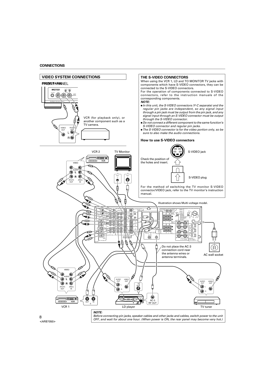
THE S-VIDEO CONNECTORS
When using the VCR 1, LD and TO MONITOR TV jacks with components which have
For the operation of components connected to
NOTE:
÷In this unit, the
÷Do not connect a different component to the same function's
÷The
How to use S-VIDEO connectors
Check the position of the holes and insert.
For the method of switching the TV monitor
V
VIDEO
| L | V |
|
| |
R | V | V |
| Illustration shows | |
|
|
L |
|
|
|
|
|
|
|
|
|
|
|
|
|
|
|
|
|
|
|
|
|
|
|
R |
|
|
|
|
|
|
| CONTROL |
|
|
|
|
|
|
|
|
|
|
|
|
|
|
|
|
|
|
|
| VIDEO OUT |
| SYSTEM CONTROL |
|
| SUB WOOFER |
|
| CENTER |
| SPEAKER |
| TWO VOLTAGE | SELECTORS | |||||
|
|
| GND |
|
|
|
|
|
|
|
|
|
|
|
|
|
|
| |||||
|
|
|
| TO MONITOR TV |
|
|
| IR OUT |
|
| PRE |
|
| PRE |
| SELECTOR |
|
|
|
|
| ||
|
|
|
|
|
|
|
|
|
|
|
|
|
|
|
| 110V |
|
|
| ||||
V | PAL | NTSC |
|
|
|
|
|
| MAIN- |
|
|
| OUT |
|
| OUT |
| SPEAKER |
| 120~127V |
|
| |
|
|
| PHONO |
|
|
|
| IN | REPEATER |
|
|
|
|
|
| I+II | IMPEDANCE |
|
|
|
|
| |
|
|
|
|
|
|
|
|
|
|
|
|
|
|
| CENTER |
| 8Ω~16Ω |
|
|
|
|
| |
L |
|
| IN |
|
|
| OUT |
|
|
|
|
|
|
|
|
| /SPEAKER |
|
|
|
|
| |
FM 50kHz | 100kHz |
|
|
|
|
|
|
|
|
|
|
| SPEAKERS |
|
|
|
|
|
| ||||
|
|
|
|
|
|
|
|
|
|
|
|
|
| CAUTION: |
|
|
|
|
| ||||
| /50μS | /75μS |
|
|
|
| VCR2 | OUT |
|
|
|
|
|
|
|
|
|
|
|
|
|
| |
| AM 9kHz | 10kHz | REC |
|
|
|
|
|
|
|
|
|
|
| I ONLY | THE POWER |
|
| 220V |
| 240V | ||
R | CHANNEL | STEP |
|
|
| IN |
|
|
|
|
|
|
|
|
| SUPPLY CORD SHOULD | 220V |
|
| ||||
|
|
|
| 1 |
| 2 |
|
|
|
|
|
|
| BE DISCONNECTED |
| 110V | |||||||
| /FM DE- | EMPHASIS | TAPE2 |
|
|
|
|
|
|
|
|
|
|
|
|
|
| BEFORE CHANGING |
| 240V |
| ||
|
|
|
|
|
|
|
| MINI- |
|
|
|
|
|
|
|
| THE VOLTAGE |
|
|
|
|
| |
L |
|
| MONI- |
|
|
|
|
| REPEATER |
|
|
|
|
|
|
| SELECTOR. |
|
|
|
|
| |
|
| TOR |
|
|
| OUT |
| S |
|
|
| I |
| II | SEE |
| A |
|
|
|
|
| |
|
| FM | PLAY |
|
|
| VCR1 |
| OUT |
|
|
|
| INSTRUCTION |
|
|
|
|
|
| |||
|
| BAL |
|
|
|
|
|
|
|
|
|
|
|
|
| MANUAL |
|
|
|
|
|
|
|
R |
| 300Ω REC |
|
|
|
|
|
|
|
|
|
|
|
|
|
|
|
|
|
|
|
| |
|
|
|
|
|
| IN |
| S |
|
|
|
|
|
|
| R |
| L |
|
|
|
| |
|
|
|
|
|
|
|
|
|
|
|
|
|
|
|
|
|
|
|
| ||||
|
|
|
|
|
|
|
|
| IN |
|
|
|
|
|
|
|
|
|
|
|
| ||
|
|
| TAPE1 |
|
|
|
|
|
|
|
|
|
|
|
|
|
|
|
|
|
|
|
|
|
| FM |
|
|
|
| LD |
|
|
|
|
|
|
|
|
|
|
|
| SWITCHED |
|
| |
|
| UNBAL |
|
|
|
| S |
|
|
|
|
|
|
|
|
|
|
|
| ||||
|
|
|
|
| IN |
|
|
|
|
|
|
|
|
| FRONT |
| TOTAL 100W MAX | ||||||
|
| 75Ω | PLAY |
|
|
|
| IN |
|
|
|
|
|
|
|
|
| ||||||
|
|
|
|
|
|
|
|
|
|
|
|
|
|
|
| SPEAKERS |
|
|
|
|
| ||
|
|
|
|
|
|
|
|
|
|
|
|
| SPEAKER |
|
|
|
|
|
|
|
|
| |
|
|
|
|
|
|
|
|
|
|
|
|
|
|
|
|
|
|
|
|
|
|
| |
V |
| GND | CD IN |
|
|
| TV |
|
| TO |
|
| IMPEDANCE |
|
|
|
|
|
|
|
|
|
|
|
|
|
|
| /SAT |
| S | MONITOR | 8Ω~16Ω | R | L | REAR |
|
|
| UNSWITCHED |
| ||||||
|
|
|
|
|
|
| IN |
| OUT | TV | DIGITAL IN | RF IN | /SPEAKER |
|
|
| 100W MAX |
|
| ||||
|
|
|
|
|
|
|
|
|
|
|
|
|
|
| SPEAKERS | R |
| L |
|
| |||
|
|
| R | L | R | L | VIDEO |
|
|
| TV |
|
|
|
|
|
|
|
|
|
| ||
R |
| AM |
|
|
| /SAT |
| LD |
|
|
|
|
|
|
|
|
|
| |||||
|
| LOOP |
|
|
|
| SEE INSTRUCTION MANUAL |
|
|
|
|
|
|
|
|
| B |
|
|
|
|
| |
|
|
|
|
|
|
|
|
|
|
|
|
|
|
|
|
|
| CAUTION: |
|
| |||
L |
| ANTENA |
|
|
|
|
|
|
|
|
|
|
|
|
|
|
| SPEAKER IMPEDANCE |
|
|
| ||
|
|
|
|
|
|
|
|
|
|
|
|
|
|
|
|
|
| 8Ω~16Ω/SPEAKER |
| DO NOT CONNECT |
| ||
| ANTENNA |
|
|
|
|
|
|
|
|
|
|
|
|
|
|
|
|
| TV SET CR MONITOR. | ||||
|
|
|
|
|
|
|
|
|
|
|
|
|
|
|
|
|
|
| AC OUTLETS | ||||
|
|
|
|
| R | L | V | V |
|
|
|
|
|
|
|
|
|
|
|
|
|
|
|
Do not place the
the antenna wires or AC wall socket antenna terminals.
V
L
R
AUDIO
L
L
R | L | V |
R | AUDIO | VIDEO |
| OUT | OUT |
L
R
V
AUDIO VIDEO
R
L
S
OUT OUT
(PLAY) (REC)
OUT IN
VCR
OUT
R
OUT IN
S
RF OUT
L
R
VCR 1
8
<ARB7050>
LD player | TV tuner |
NOTE:
Before connecting pin jacks, speaker cables and other jacks and cables, switch power to the unit OFF, and wait for about one hour. (When power is ON, the rear panel may become very hot.)