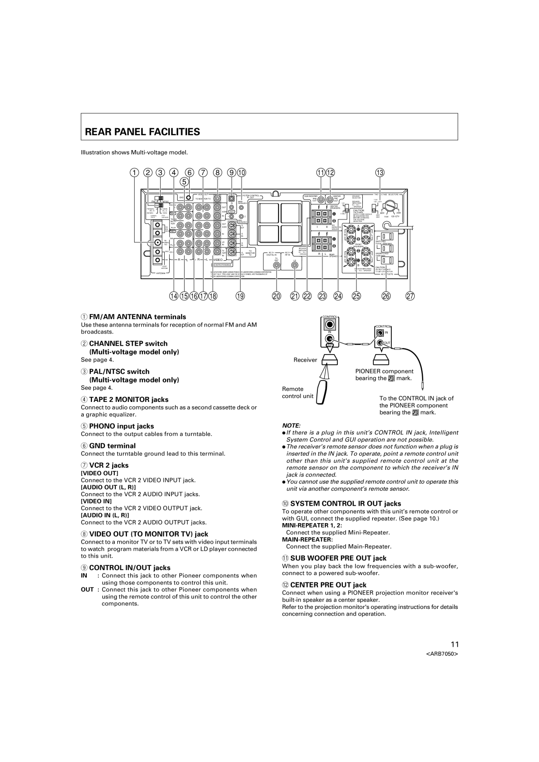
REAR PANEL FACILITIES
Illustration shows Multi-voltage model.
1 | 2 | 3 | 4 | 6 | 7 | 8 | 9 | 10 |
| 11 12 |
| 13 |
|
|
| ||
|
|
|
| 5 |
|
|
|
|
|
|
|
|
|
|
|
|
|
|
|
|
|
| VIDEO OUT |
| CONTROL | SYSTEM CONTROL | SUB WOOFER |
| CENTER | SPEAKER | TWO VOLTAGE | SELECTORS | |||
|
|
|
|
|
|
|
|
|
|
|
|
| |||||
|
|
|
| GND | TO MONITOR TV |
|
| IR OUT | PRE |
|
| PRE | SELECTOR |
|
|
|
|
|
|
|
|
|
|
|
|
|
|
| 110V |
|
|
| |||
| PAL | NTSC |
|
|
|
|
| MAIN- | OUT |
|
| OUT | SPEAKER | 120~127V |
|
|
|
|
|
| PHONO |
|
|
| IN | REPEATER |
|
|
| I+II | IMPEDANCE |
|
|
|
|
|
|
|
|
|
|
|
|
|
|
| CENTER | 8Ω~16Ω |
|
|
|
| |
|
|
| IN |
|
| OUT |
|
|
|
|
| /SPEAKER |
|
|
|
| |
| FM 50kHz | 100kHz |
|
|
|
|
|
|
| SPEAKERS |
|
|
|
|
| ||
|
|
|
|
|
|
|
|
|
| CAUTION: |
|
|
|
| |||
| /50μS | /75μS |
|
|
| VCR2 | OUT |
|
|
|
|
|
|
|
|
| |
| AM 9kHz | 10kHz | REC |
|
|
|
|
|
| I ONLY | THE POWER | 220V |
| 240V | |||
| CHANNEL | STEP |
|
| IN |
|
|
|
|
| SUPPLY CORD SHOULD | 220V |
|
|
| ||
|
|
|
| 1 | 2 |
|
|
|
| BE DISCONNECTED | 110V |
| |||||
| /FM DE- | EMPHASIS |
|
|
|
|
|
|
|
| BEFORE CHANGING | 240V | |||||
| TAPE2 |
|
|
|
|
|
|
|
|
|
|
|
| ||||
|
|
|
|
|
|
| MINI- |
|
|
|
| THE VOLTAGE |
|
|
|
| |
|
|
| MONI- |
|
|
|
| REPEATER |
|
|
|
| SELECTOR. |
|
|
|
|
|
|
| TOR |
|
| OUT |
| S |
|
|
| SEE | A |
|
|
|
|
|
| FM |
|
|
| VCR1 |
|
| I | II |
|
|
|
| |||
|
| PLAY |
|
|
| OUT |
| INSTRUCTION |
|
|
|
|
| ||||
BAL |
|
|
|
|
|
|
|
|
|
|
| MANUAL |
|
|
|
|
300Ω REC |
|
|
|
|
|
|
|
|
|
|
|
|
|
|
| |
|
|
|
|
| IN | S |
|
|
|
|
|
| R |
| L |
|
|
|
|
|
|
| IN |
|
|
|
|
|
|
|
| ||
| TAPE1 |
|
|
|
|
|
|
|
|
|
|
|
|
|
|
|
FM |
|
|
|
| LD |
|
|
|
|
|
|
|
|
|
| SWITCHED |
UNBAL |
|
|
|
| S |
|
|
|
|
|
|
|
|
| ||
75Ω | PLAY |
|
|
| IN |
|
|
|
|
|
|
| FRONT |
| TOTAL 100W MAX | |
|
|
| IN |
|
|
|
|
|
|
|
|
| ||||
|
|
|
|
|
|
|
|
|
| SPEAKER |
|
|
| SPEAKERS |
|
|
|
|
|
|
|
|
|
|
|
|
|
|
|
|
|
| |
GND | CD IN |
|
|
| TV |
| TO |
|
| IMPEDANCE |
|
|
|
|
|
|
|
|
| S | 8Ω~16Ω |
|
|
|
|
|
| ||||||
|
|
|
| /SAT | MONITOR | R | L REAR |
|
|
| UNSWITCHED | |||||
|
|
|
|
| IN | OUT | TV | DIGITAL IN | RF IN | /SPEAKER |
|
|
| 100W MAX | ||
|
|
|
|
|
|
|
|
|
|
| SPEAKERS | R |
| L | ||
| R | L | R | L | VIDEO |
|
| TV |
|
|
|
|
|
| ||
AM |
|
| /SAT |
| LD |
|
|
|
|
|
| |||||
LOOP |
|
|
|
| SEE INSTRUCTION MANUAL |
|
|
|
|
|
|
|
| B |
|
|
|
|
|
|
|
|
|
|
|
|
|
|
|
| CAUTION: | ||
ANTENA |
|
|
|
|
|
|
|
|
|
|
|
|
| SPEAKER IMPEDANCE |
| |
|
|
|
|
|
|
|
|
|
|
|
|
|
| DO NOT CONNECT | ||
|
|
|
|
| MANUFACTURED UNDER LICENSE FROM DOLBY LABORATORIES LICENSING CORPORATION. |
|
|
|
|
| 8Ω~16Ω/SPEAKER |
| TV SET CR MONITOR. | |||
ANTENNA |
|
|
|
|
|
|
|
|
|
|
| |||||
|
|
|
|
|
|
|
|
|
|
| AC OUTLETS | |||||
|
|
|
|
|
|
|
|
|
|
|
| |||||
|
|
|
|
| DOLBY LABORATORIES LICENSING CORPORATION. |
|
|
|
|
|
|
|
|
|
| |
14 | 15 16 17 18 | 19 |
1FM/AM ANTENNA terminals
Use these antenna terminals for reception of normal FM and AM broadcasts.
2CHANNEL STEP switch
20 | 21 | 22 | 23 | 24 | 25 | 26 | 27 |
CONTROL |
|
| CONTROL |
IN | IN |
OUT | OUT |
|
See page 4.
3PAL/NTSC switch
See page 4.
4TAPE 2 MONITOR jacks
Connect to audio components such as a second cassette deck or a graphic equalizer.
5PHONO input jacks
Receiver
Remote control unit
NOTE:
PIONEER component bearing the Î mark.
To the CONTROL IN jack of the PIONEER component bearing the Î mark.
Connect to the output cables from a turntable.
6GND terminal
Connect the turntable ground lead to this terminal.
7VCR 2 jacks
[VIDEO OUT]
Connect to the VCR 2 VIDEO INPUT jack.
[AUDIO OUT (L, R)]
Connect to the VCR 2 AUDIO INPUT jacks.
[VIDEO IN]
Connect to the VCR 2 VIDEO OUTPUT jack.
[AUDIO IN (L, R)]
Connect to the VCR 2 AUDIO OUTPUT jacks.
8VIDEO OUT (TO MONITOR TV) jack
Connect to a monitor TV or to TV sets with video input terminals to watch program materials from a VCR or LD player connected to this unit.
9CONTROL IN/OUT jacks
IN : Connect this jack to other Pioneer components when using those components to control this unit.
OUT : Connect this jack to other Pioneer components when using the remote control of this unit to control the other components.
÷If there is a plug in this unit’s CONTROL IN jack, Intelligent System Control and GUI operation are not possible.
÷The receiver’s remote sensor does not function when a plug is inserted in the IN jack. To operate, point a remote control unit other than this unit's supplied remote control unit at the remote sensor on the component to which the receiver’s IN jack is connected.
÷You cannot use the supplied remote control unit to operate this unit via another component’s remote sensor.
0SYSTEM CONTROL IR OUT jacks
To operate other components with this unit’s remote control or with GUI, connect the supplied repeater. (See page 10.)
Connect the supplied
Connect the supplied
-SUB WOOFER PRE OUT jack
When you play back the low frequencies with a
=CENTER PRE OUT jack
Connect when using a PIONEER projection monitor receiver's
Refer to the projection monitor's operating instructions for details concerning connection and operation.
11
<ARB7050>