004917-2 specifications
Generac Power Systems 004917-2 is a noteworthy addition to the realm of home power solutions, designed to provide reliable backup power during outages and enhance energy management for residential users. This model is recognized for its robust engineering and advanced features, making it a preferred choice for homeowners seeking uninterrupted power supply.One of the standout characteristics of the 004917-2 is its quiet operation, achieved through innovative noise-reduction technology. This feature ensures that users can enjoy a peaceful environment without the disruptive sounds often associated with traditional generators. The unit is designed not only for functionality but also for discretion, seamlessly blending into residential settings.
Built with a powerful engine, the 004917-2 delivers an impressive wattage capacity, ensuring that essential appliances such as refrigerators, lights, and heating systems can function smoothly during power outages. Its automatic transfer switch capability is a significant technological advancement, allowing the generator to detect power loss and activate without user intervention. This means that homeowners can have peace of mind knowing that their critical systems will remain operational when most needed.
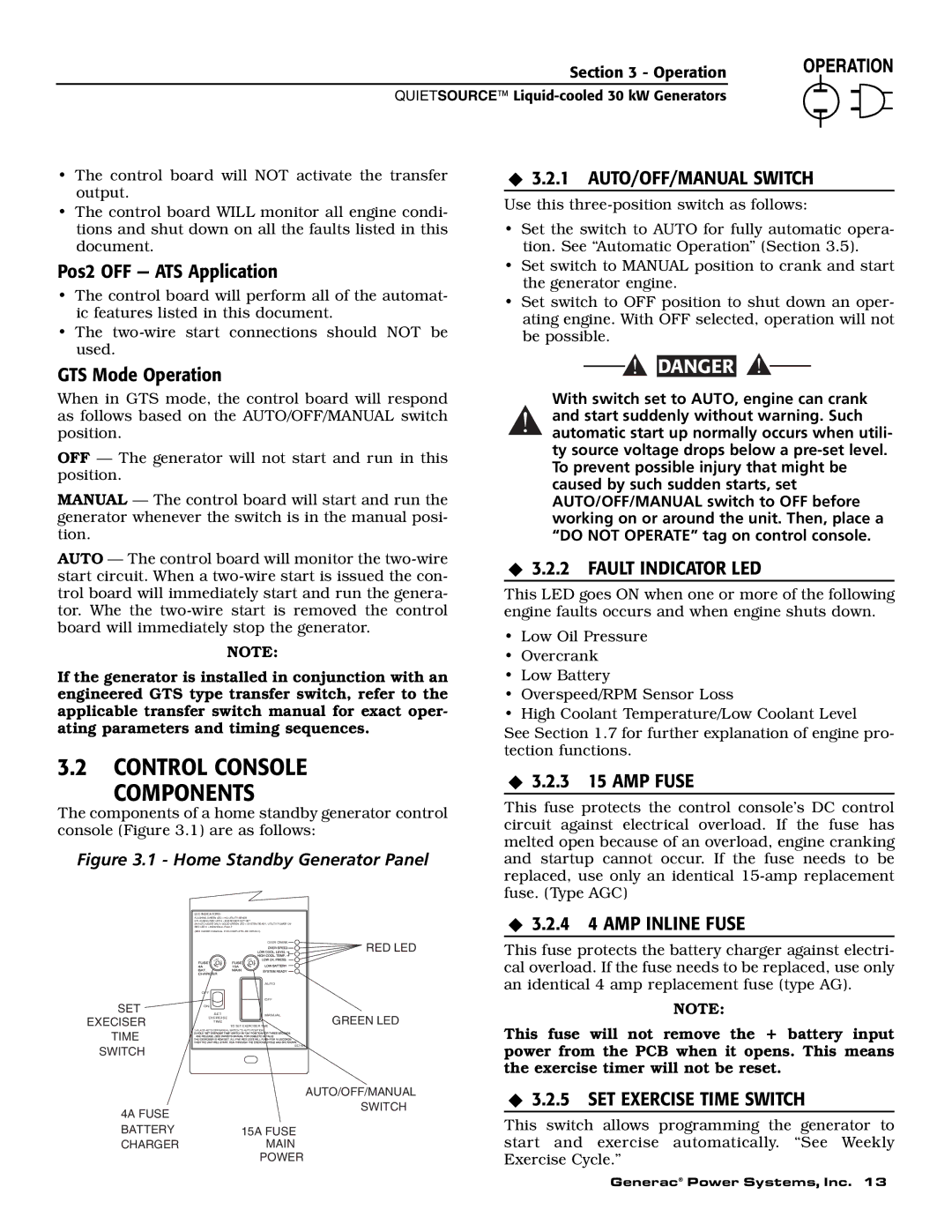
Another notable feature of the Generac 004917-2 is its user-friendly control panel, equipped with digital indicators that provide real-time monitoring of the generator's performance. This interface allows users to easily assess power usage, fuel levels, and maintenance schedules, empowering them with the information necessary to manage their energy needs effectively.
Moreover, the 004917-2 is designed for fuel efficiency, incorporating eco-friendly technologies that optimize fuel consumption while delivering high power output. This design not only helps to reduce operational costs but also minimizes the environmental impact.
In terms of durability, the unit boasts a corrosion-resistant exterior that enhances its lifespan, making it suitable for various climates and conditions. Generac's commitment to quality assurance is evident in the rigorous testing that each model undergoes before reaching the consumer market.
In summary, the Generac Power Systems 004917-2 stands out as a reliable and efficient solution for homeowners looking for dependable backup power. With its quiet operation, powerful performance, automatic transfer capabilities, user-friendly interface, fuel efficiency, and robust construction, it meets the demands of modern energy use while offering peace of mind during unexpected outages.

