Section 1 - General Information
1.1GENERATOR
This equipment is a
If this generator is used to power electrical load circuits normally powered by a UTILITY power source, it is required by code to install a trans- fer switch. The transfer switch must effectively isolate the electric system from the utility distri- bution system when the generator is operating (NEC 701). Failure to isolate an electrical system by such means results in damage to the genera- tor and may also result in injury or even death to utility power workers due to backfeed of electrical energy.
1.2TRANSFER SWITCH
This generator system may include a matched auto- matic transfer switch which is intended to be used in conjunction with the generator. It is supplied in a NEMA 3R enclosure. The NEMA 3R enclosure is weather proof and can be used indoors or outdoors. Follow these rules:
•Install the transfer switch on a firm, sturdy sup- porting structure.
•To prevent switch distortion, level the switch if necessary. This can be done by placing washers between the switch enclosure and the mounting surface.
•Never install the switch where water or any corro- sive substance might drip onto the enclosure.
•Protect the switch at all times against excessive moisture, dust, dirt, lint, construction grit and cor- rosive vapors.
If a transfer switch is not included, one may be pur- chased separately from an Authorized Dealer.
1.3AUTOMATIC SYSTEM OPERATION
When this generator, along with a transfer switch, has been installed and interconnected, a circuit board in the generator panel constantly monitors UTILITY power source voltage. Should that voltage drop below a preset value, and remain at such a low state for a preset amount of time, the generator cranks and starts. After the generator starts, the transfer switch transfers load circuits so the generator can power them.
When UTILITY source voltage has been restored, the switch
Please reference the transfer switch manual for spe- cific information.
1.4GENERATOR AC CONNECTION
SYSTEMS
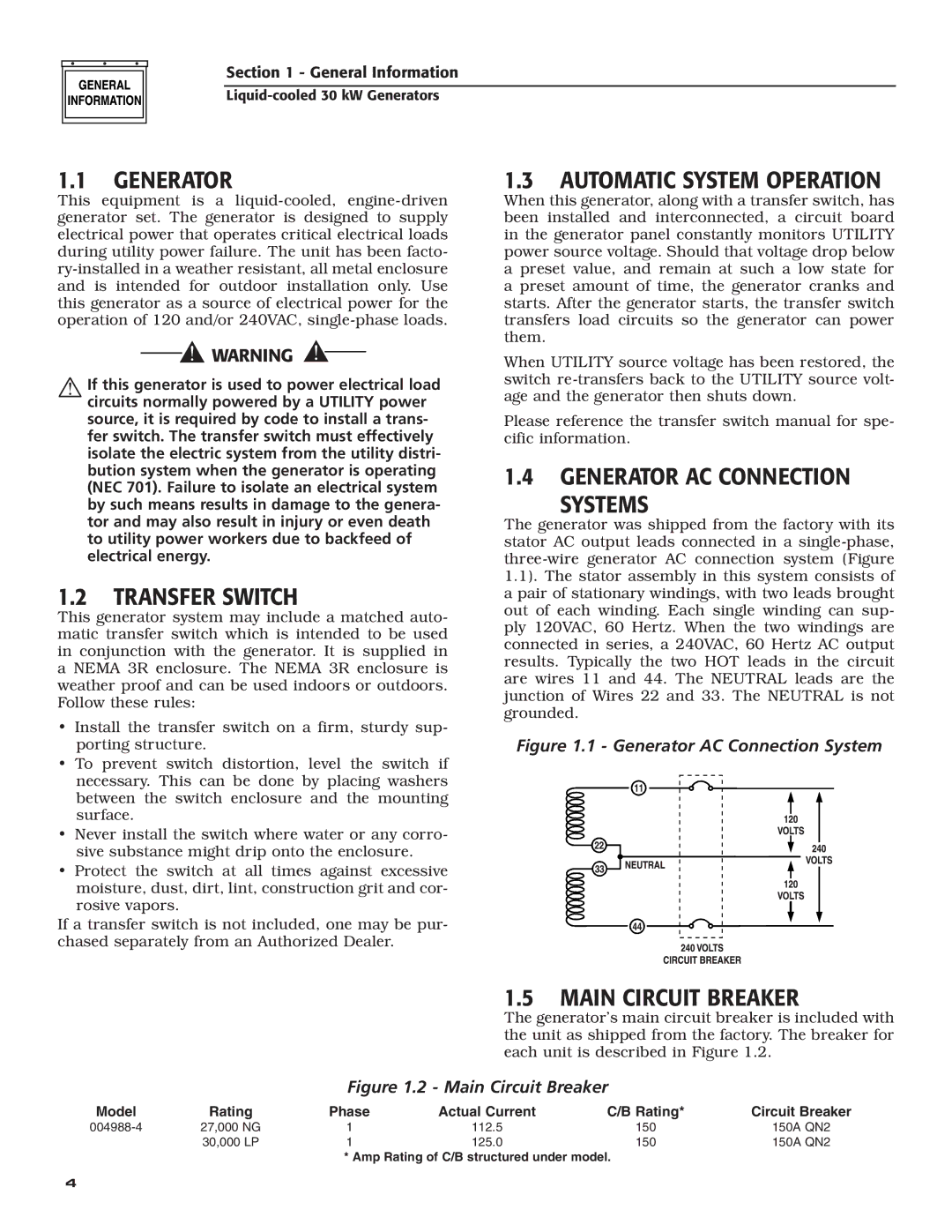
The generator was shipped from the factory with its stator AC output leads connected in a
Figure 1.1 - Generator AC Connection System
|
|
| 1.5 | MAIN CIRCUIT BREAKER | |
|
|
| The generator’s main circuit breaker is included with | ||
|
|
| the unit as shipped from the factory. The breaker for | ||
|
|
| each unit is described in Figure 1.2. | ||
|
| Figure 1.2 - Main Circuit Breaker |
| ||
Model | Rating | Phase | Actual Current | C/B Rating* | Circuit Breaker |
27,000 NG | 1 | 112.5 | 150 | 150A QN2 | |
| 30,000 LP | 1 | 125.0 | 150 | 150A QN2 |
* Amp Rating of C/B structured under model.
4