Section 3 - Operation
Guardian
GTS Mode Operation
When in GTS mode, the control board will respond as follows based on the generator AUTO/OFF/MANU- AL switch position.
OFF — The generator will not start and run in this position.
MANUAL — The control board will start and run the generator whenever the switch is in the manual posi- tion.
AUTO — The control board will monitor the
NOTE:
If the generator is installed in conjunction with an engineered GTS type transfer switch, refer to the applicable transfer switch manual for exact oper- ating parameters and timing sequences.
For proper battery charger operation, it will be nec- essary to supply a fused 240VAC utility fed supply to terminals N1 and N2 in the control panel.
![]()
![]() DANGER
DANGER
With switch set to AUTO, engine can crank
!and start suddenly without warning. Such automatic start up normally occurs when utili- ty source voltage drops below a
3.2.2 FAULT INDICATOR LEDS
(SEE CHART ON PAGE 14)
These LEDs turn ON when one or more of the follow- ing engine faults occurs and the engine shuts down.
•Low Oil Pressure
•Overcrank
•Low Battery
•Overspeed/Engine Speed Signal Fault
•High Coolant Temperature/Low Coolant Level
See Section 1.7 for further explanation of engine pro- tection functions.
3.2CONTROL CONSOLE
COMPONENTS
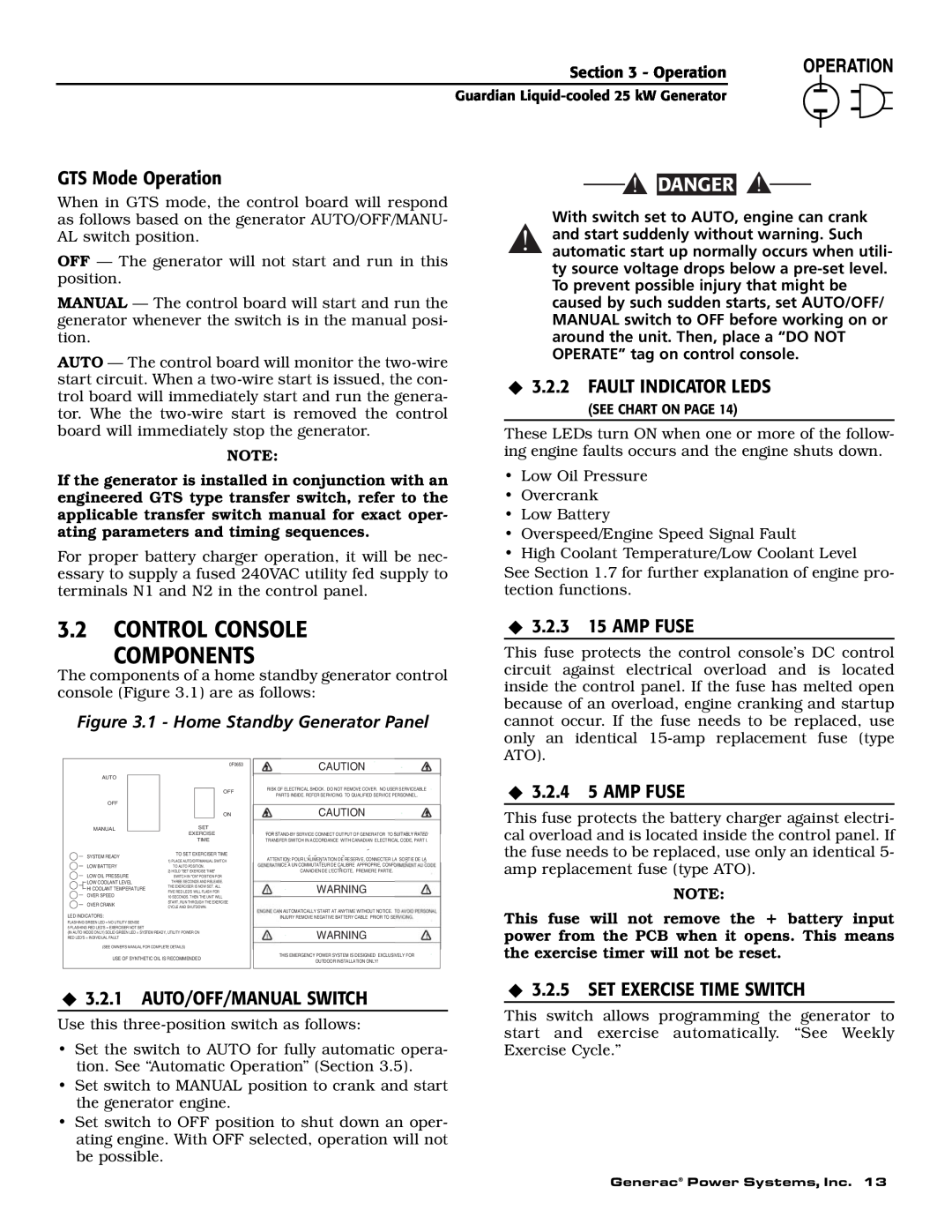
The components of a home standby generator control console (Figure 3.1) are as follows:
Figure 3.1 - Home Standby Generator Panel
3.2.3 15 AMP FUSE
This fuse protects the control console’s DC control circuit against electrical overload and is located inside the control panel. If the fuse has melted open because of an overload, engine cranking and startup cannot occur. If the fuse needs to be replaced, use only an identical
AUTO
OFF
MANUAL
SYSTEM READY
LOW BATTERY
LOW OIL PRESSURE
![]() LOW COOLANT LEVEL
LOW COOLANT LEVEL
![]() HI COOLANT TEMPERATURE
HI COOLANT TEMPERATURE ![]() OVER SPEED
OVER SPEED
OVER CRANK
LED INDICATORS:
0F0653
OFF
ON
SET
EXERCISE
TIME
TO SET EXERCISER TIME
1)PLACE AUTO/OFF/MANUAL SWITCH TO AUTO POSITION.
2)HOLD "SET EXERCISE TIME" SWITCH IN "ON" POSITION FOR
THREE SECONDS AND RELEASE. THE EXERCISER IS NOW SET. ALL FIVE RED LED'S WILL FLASH FOR
10 SECONDS. THEN THE UNIT WILL START, RUN THROUGH THE EXERCISE CYCLE AND SHUTDOWN.
CAUTION
RISK OF ELECTRICAL SHOCK. DO NOT REMOVE COVER. NO USER SERVICEABLE
PARTS INSIDE. REFER SERVICING TO QUALIFIED SERVICE PERSONNEL.
CAUTION
FOR
ATTENTION: POUR L'ALIMENTATION DE RESERVE, CONNECTER LA SORTIE DE LA ICE A UN COMMUTATEUR DE CALIBRE APPROPRIE, CONFO
CANADIEN DE L'ECTRICITE, PREMIERE PARTIE.
WARNING
N AUTOMATICALLY START AT ANYTIME WITHOUT NOTICE. T
INJURY REMOVE NEGATIVE BATTERY CABLE PRIOR TO SE
3.2.4 5 AMP FUSE
This fuse protects the battery charger against electri- cal overload and is located inside the control panel. If the fuse needs to be replaced, use only an identical 5- amp replacement fuse (type ATO).
NOTE:
This fuse will not remove the + battery input
FLASHING GREEN LED = NO UTILITY SENSE
5 FLASHING RED LED'S = EXERCISER NOT SET
(IN AUTO MODE ONLY) SOLID GREEN LED = SYSTEM READY, UTILITY POWER ON RED LED'S = INDIVIDUAL FAULT
(SEE OWNER'S MANUAL FOR COMPLETE DETAILS)
USE OF SYNTHETIC OIL IS RECOMMENDED
WARNING
THIS EMERGENCY POWER SYSTEM IS DESIGNED EXCLUSIVELY FOR
OUTDOOR INSTALLATION ONLY!
power from the PCB when it opens. This means the exercise timer will not be reset.
3.2.1 AUTO/OFF/MANUAL SWITCH
Use this
•Set the switch to AUTO for fully automatic opera- tion. See “Automatic Operation” (Section 3.5).
•Set switch to MANUAL position to crank and start the generator engine.
•Set switch to OFF position to shut down an oper- ating engine. With OFF selected, operation will not be possible.
3.2.5 SET EXERCISE TIME SWITCH
This switch allows programming the generator to start and exercise automatically. “See Weekly Exercise Cycle.”
Generac® Power Systems, Inc. 13