Panel Features
This section describes:
•Rear Panel Connections
•Front Panel Controls and Indicators
Rear Panel Connections
1
MSW 4SV rs
|
| I | O |
|
POWER 1 | 3 | N | U | A |
P | T | |||
12V |
| U | P |
|
.5A MAX |
| T | U |
|
|
| S | T |
|
|
|
| S |
|
2 | 4 |
|
| B |
2
Tx Rx
CONTACT
1 | 2 | 3 | 4 |
75
MSW 4SV rs
MSW 4V rs
POWER 1 | 3 |
12V
.5A MAX
2 4
|
| 4 | 3 |
|
|
| |
I | O |
|
|
N | U |
| Tx Rx |
P | T | A |
|
U | P |
|
T | U | CONTACT |
S | T | |
| S |
|
B | 1 | 2 | 3 | 4 |
|
2
7 | 6 | 1 | 3 |
MSW 4V rs |
|
|
|
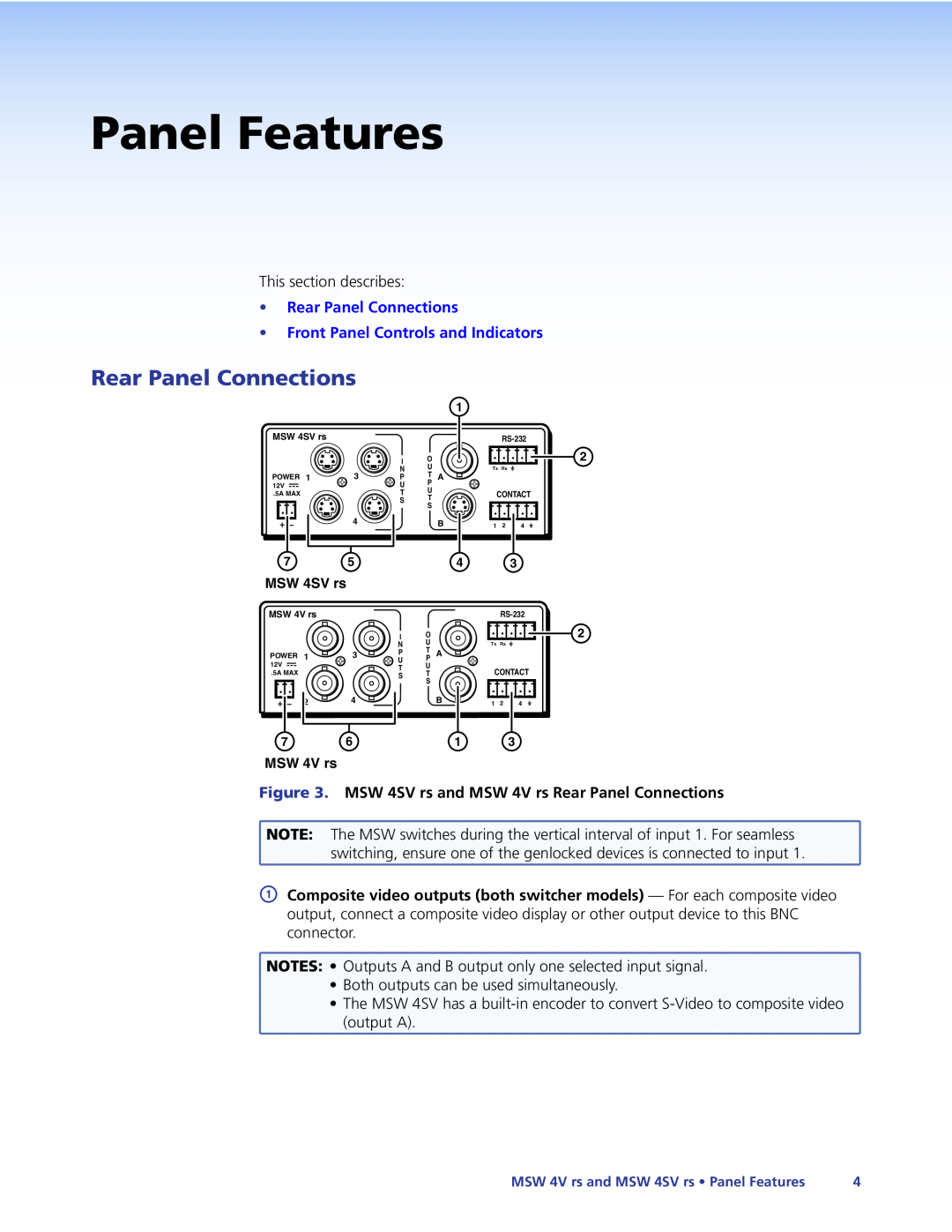
Figure 3. MSW 4SV rs and MSW 4V rs Rear Panel Connections
![]() NOTE: The MSW switches during the vertical interval of input 1. For seamless
NOTE: The MSW switches during the vertical interval of input 1. For seamless
switching, ensure one of the genlocked devices is connected to input 1.
AComposite video outputs (both switcher models) — For each composite video output, connect a composite video display or other output device to this BNC connector.
![]() NOTES: • Outputs A and B output only one selected input signal.
NOTES: • Outputs A and B output only one selected input signal.
• Both outputs can be used simultaneously.
• The MSW 4SV has a
(output A).
MSW 4V rs and MSW 4SV rs • Panel Features | 4 |
