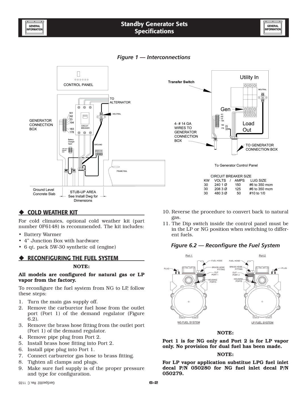
005219-0 specifications
Generac Power Systems 005219-0 is a robust and versatile backup power generator designed for residential and commercial applications. Known for its reliability and advanced features, this generator ensures that you have a dependable power source when you need it the most, particularly during unexpected outages.One of the standout features of the Generac 005219-0 is its powerful engine. It is equipped with a 22 kW capacity, which is sufficient to power essential appliances and systems in your home or business. This power allows for the simultaneous operation of multiple devices, such as refrigerators, air conditioning units, and electronics, without the worry of overloading the system.
Generac’s patented Quiet-Test Technology is another significant characteristic of the 005219-0, which enables the generator to run at a lower RPM during weekly self-tests. This feature not only ensures that the generator is in optimal condition but also minimizes noise, making it less intrusive for homeowners while providing peace of mind that the generator is ready when needed.
The generator utilizes an automatic transfer switch, which instantly switches your home's power source from the grid to the generator in the event of a power failure. This seamless transition prevents any disruption in your daily activities and protects sensitive electronics from power surges.
Additionally, Generac is known for its tough design and weather-resistant features. The generator is constructed with durable materials to withstand various weather conditions, making it suitable for outdoor placement. Furthermore, the unit typically comes with a corrosion-resistant aluminum enclosure, ensuring longevity and reduced maintenance.
The 005219-0 also includes user-friendly control options, which are facilitated by a digital controller that provides easy monitoring and management of the generator’s functions. This capability allows users to track power consumption, manage maintenance schedules, and diagnose any potential issues quickly.
Lastly, Generac stands behind its products with comprehensive warranties, providing customers with assurance and confidence in their investment. With excellent customer service and support, owning a Generac generator like the 005219-0 means you are investing in a reliable power solution that meets your energy needs effectively.

