Genie M-4500, M-4700 owner manual Install Photo EYE Safety System, Install Wall Control Panel

Models: M-4700 M-4500

1 32
Download 32 pages 53.32 Kb
Page 14
Image 14

8-10. INSTALL PHOTO EYE SAFETY SYSTEM

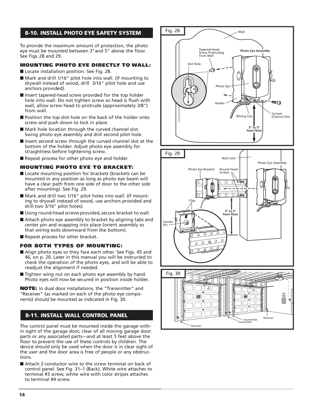
To provide the maximum amount of protection, the photo eye must be mounted between 3"and 5" above the floor. See Figs. 28 and 29.

Fig. 28

Wall

Tapered-Head

Photo Eye Assembly

Screw Protruding


from Wall


MOUNTING PHOTO EYE DIRECTLY TO WALL:

■ Locate installation position. See Fig. 28.

■ Mark and drill 1/16" pilot hole into wall. (If mounting to

drywall instead of wood, drill 3/16" pilot hole and use

anchors provided).

■ Insert tapered-head screw provided for the top holder

hole into wall. Do not tighten screw so head is flush with

wall, allow screw head to protrude (approximately 3/8")

from wall.

■ Position the top slot hole on the back of the holder onto

screw and push down to lock in place.

Slot Hole

Photo Eye

Holder

Wiring Clip

Curved Channel Slot

■ Mark hole location through the curved channel slot.

Swing photo eye assembly and drill second pilot hole.

■ Insert second screw through the curved channel slot at the

bottom of the holder. Adjust photo eye assembly for

3” to 5”

from Floor

straightness before tightening screw.

■ Repeat process for other photo eye and holder.

MOUNTING PHOTO EYE TO BRACKET:

Locate mounting position for brackets (brackets can be mounted in any position as long as photo eye beam will have a clear path from one side of door to the other side after mounting). See Fig. 29.

Mark and drill two 1/16" pilot holes into wall. (If mount- ing to drywall instead of wood, use anchors provided and drill two 3/16" pilot holes).

Using round-head screws provided, secure bracket to wall.

Attach photo eye assembly to bracket by aligning tabs and center pin and snapping into place (orient assembly so that wiring exits downward from the bottom).

Repeat process for other bracket.

FOR BOTH TYPES OF MOUNTING:

Fig. 29


Wall Joist

Photo Eye Bracket

Round-Head


Screws

Clips

3” to 5”

from Floor

Center

Pin

Photo Eye Assembly

Align photo eyes so they face each other. See Figs. 45 and 46, on p. 20. Later in this manual you will be instructed to check the operation of the photo eyes, and will be able to readjust the alignment if needed.

Tighten wing nut on each photo eye assembly by hand. Photo eyes will now be secured in position inside holder.

NOTE: In dual door installations, the "Transmitter" and "Receiver" (as marked on each of the photo eye compo- nents) should be mounted as indicated in Fig. 30.

8-11. INSTALL WALL CONTROL PANEL

The control panel must be mounted inside the garage with- in sight of the garage door, clear of all moving garage door parts or any associated parts—and at least 5 feet above the floor to prevent the use of these controls by children. The device should only be used when the door is in clear sight of the user and the door area is free of people or any obstruc- tions.

Attach 2-conductor wire to the screw terminal on back of control panel. See Fig. 31–1 (Back). White wire attaches to terminal #3 screw, white wire with color stripes attaches to terminal #4 screw.

14

Fig. 30

Transmitter

Transmitter

Receiver

Receiver

Page 14
Image 14
Genie M-4500, M-4700 Install Photo EYE Safety System, Install Wall Control Panel, Mounting Photo EYE Directly to Wall

M-4700, M-4500 specifications

The Genie M-4500 and M-4700 are advanced aerial work platforms designed to enhance productivity and safety in various industrial and construction applications. Both models are well-known for their reliability and user-friendly features, making them popular choices for operators seeking efficient solutions for elevated work tasks.

The Genie M-4500 is a compact lift designed to elevate workers and materials up to 45 feet. One of its standout features is its impressive lifting capacity of up to 1,000 pounds, enabling it to safely handle heavy loads and multiple workers at once. The M-4500 is equipped with a unique four-wheel drive system, providing excellent traction on uneven surfaces, which is particularly beneficial for outdoor applications. The hydraulic scissor lift technology utilized in the M-4500 allows for stable and smooth vertical movements, minimizing the risk of accidents and enhancing overall safety.

On the other hand, the Genie M-4700 offers even greater lifting capabilities, reaching up to 47 feet with a comparable weight capacity of up to 1,000 pounds. With its extended platform size, the M-4700 is designed for bigger work areas, accommodating more tools and equipment. This model incorporates Genie’s advanced automatic leveling system, which ensures that the platform remains stable during operation, an essential feature when working on sloped or uneven terrain. The M-4700’s power options, including electric and diesel variants, provide operators with flexibility based on the specific site requirements.

Both models feature Genie’s patented Quick Positioning System, allowing for rapid setups and adjustments, further enhancing their operational efficiency. The control systems are intuitive, designed for ease of use, ensuring that operators can navigate the platforms effortlessly. Safety is also a primary concern, with integrated fall protection features, non-slip surfaces, and emergency descent systems.

In summary, the Genie M-4500 and M-4700 are top-tier aerial work platforms that combine lifting power, stability, and user-centric design to meet the demands of modern job sites. Their robust technology, combined with advanced safety features, ensures that users can complete tasks efficiently while minimizing risks. These models cater to various applications in construction, maintenance, and more, solidifying their position as essential tools in the aerial work equipment market.