Page
M Third-party brands and names are the property of their respective owners
description of the apparatus, system, installation to which it refers
reference to the specification under which conformity is declared
Timmy Huang
We, Manufacturer/Importer full address
DECLARATION OF CONFORMITY
Responsible Party NameG.B.T. INC. U.S.A Address 17358 Railroad Street
City of Industry, CA Phone/Fax No 818 854-9338/ 818
Product Name Motherboard Model NumberGA-8GEM667
USER’S MANUAL
GA-8GEM667 Series P4 Titan-DDR Motherboard
English
Table of Content
2-/4-/6-Channel Audio Function Introduction
Item Checklist
Installing the motherboard to the chassis…
Features Summary
Chapter 1 Introduction
Hardware Monitor
HT functionality requirement content
GA-8GEM667 Series Motherboard Layout
Step Step Step
Chapter 2 Hardware Installation Process
Step 1 Step 4 Step
Step 1 Install the Central Processing Unit CPU
Step1-1 CPU Installation
Angling the
Socket
Step1-2 CPU Heat Sink Installation
Please use Intel approved cooling fan
Step 2 Install memory modules
When STR/DIMM LED is ON, do not install/remove DIMM from socket
Step 3 Install expansion cards
DDR Introduction
supply
Step 4-1 I/O Back Panel Introduction
Step 4 Connect ribbon cables, cabinet wires, and power
PS/2 Keyboard and PS/2 Mouse Connector
Audio Connectors
If you want the detail information for 2-/4-/6-channel audio setup
installation, please refer to page
$ Parallel Port and VGA Port / COMA Port
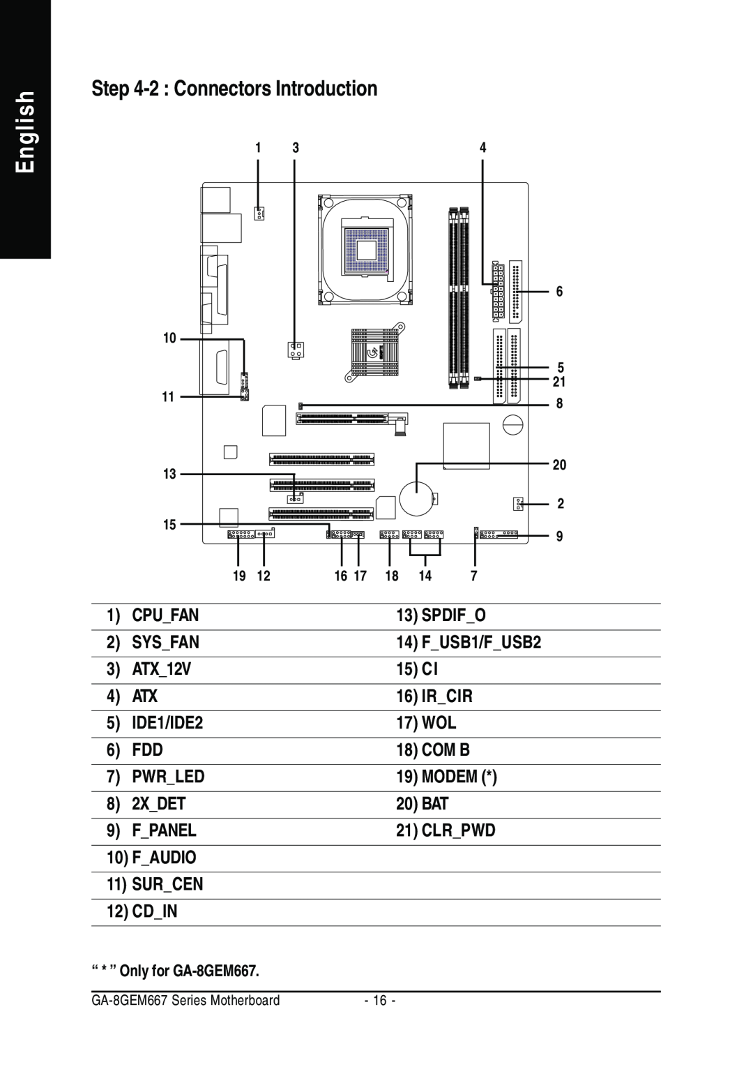
Step 4-2 Connectors Introduction
CPUFAN
13 SPDIFO
SYSFAN
1 CPUFAN CPU FAN Connector
2 SYSFAN System FAN Connector
5 IDE1/ IDE2 IDE1 / IDE2 ConnectorPrimary/Secondary
6 FDD Floppy Connector
English
7 PWRLED
9 FPANEL 2x10 pins connector
10 FAUDIO Front Audio Connector
14 FUSB1/FUSB2 FUSB1 ~ FUSB2 connector in yellow are for USB
12 CDIN CD Audio Line In
15 CI CASE OPEN
16 IRCIR
18 COM B White connector
20 BAT Battery
English
17 WOL Wake On Lan
Jumper set to close, the current status remains
1 Close Normal 1 Open Clear Password
21 CLRPWD
CONTROL KEYS
Chapter 3 BIOS Setup
ENTERING SETUP
The Main Menu For example BIOS Ver. E2
Status Page Setup Menu / Option Page Setup Menu
If you can’t find the setting you want, please press ”Ctrl+F1” to
Standard CMOS Features
Power Management Setup
PnP/PCI Configurations
Load Fail-Safe Defaults
Load Optimized Defaults
Standard CMOS Features
Date
Drive A / Drive B
Time
IDE Primary Master, Slave / IDE Secondary Master, Slave
Floppy 3 Mode Support for Japan Area
Halt on
Memory
Base Memory
Advanced BIOS Features
First / Second / Third Boot Device
Boot Up Floppy Seek
Password Check
CPU Hyper-Threading
Init Display First
Integrated
Peripherals
On-Chip Primary PCI IDE
On-Chip Secondary PCI IDE
IDE1ConductorCable
IDE2ConductorCable
USB Controller
USBKeyboardSupport
Onboard LAN Boot ROM
Onboard Serial Port
UART Mode Select
UR2Duplex Mode
Parallel Port Mode
ECPMode UseDMA
Game Port Address
Midi Port Address
Power Management Setup
ACPI Suspend Type
Soft-off by PWRBTTN
PMEEventWakeUp
Resume by Alarm
Power On By Mouse
Power On By Keyboard
KB Power ON Password
PnP/PCI Configurations
PCI 1 IRQ Assignment
PCI 2 IRQ Assignment
PCI 3 IRQ Assignment
PC Health Status
Reset Case Open Status Case Opened
Current Voltage V VCORE / +1.5V / +3.3V / +5V / +12V
Current CPU Temperature
Current CPU/SYSTEM FAN Speed RPM
CPU Warning Temperature
CPU FAN Fail Warning
SYSTEM FAN Fail Warning
Frequency/Voltage Control
This setup option will automatically assign by CPU detection
CPU Clock Ratio
CPU Host Clock Control
CPU Host Frequency MHz
Fixed PCI/AGP Frequency
Host/DRAM Clock Ratio
Memory FrequencyMhz
Top Performance
Top Performance
Load Fail-Safe Defaults
Load Fail-Safe Defaults? Y/N?Y
Load Optimized Defaults
Load Optimized Defaults? Y/N?Y
Set Supervisor/User Password
Save & Exit Setup
Save to CMOS and EXIT Y/N? Y
Exit Without Saving
Quit Without Saving Y/N? N
English
Block Diagram
Chapter 4 Technical Reference
BIOS Flash Procedureyte @BIOSTM Program to flash BIOS
3 After the floppy has been formatted completely, please press Close
STEP 3 Download BIOS and BIOS utility program
2 From Support zone, click the Motherboards BIOS & Drivers
3 We use GA-7VTX motherboard as example. Please select GA-7VTX by Model or Chipset optional menu to obtain BIOS flash files
5 At this time the screen shows the following picture, please click Extract button to unzip the files
STEP 4 Make sure the system will boot from the floppy disk
English
STEP 5 BIOS flashing
4 The BIOS flash completed. Please press ESC to exit Flash Utility
Load Setup Defaults? Y/N?N
STEP 6 Load BIOS defaults
4 Congratulate you have accomplished the BIOS flash procedure
h i f g
Q-Flash Introduction
A. What is Q-Flash Utility?
B. How to use Q-Flash?
Load BIOS From Floppy
English
II. Update BIOS NOT through Internet
@ BIOS Introduction
Gigabyte announces @ BIOS Windows BIOS live update utility
Easy TuneTM 4 Introduction
Gigabyte announces EasyTuneTM 4 Windows based Overclocking utility
2-/4-/6-Channel Audio Function
Stereo Speakers Connection and Settings
4 Channel Analog Audio Output Mode
Basic 6 Channel Analog Audio Output Mode
Line Out Line In
Advanced 6 Channel Analog Audio Output Mode using Audio Combo Kit,Optional Device Audio Combo Kit provides SPDIF output port optical & coaxis and SURROUND-KIT Rear R/L & Center/subwoofer
Basic & Advanced 6 Channel Analog Audio Output ModeNotes
connecting port
SPDIF Output Device Optional Device
English
Technical Reference
English
Chapter 5 Appendix
Appendix A Chipset Driver Installation
A. Intel Chipset Software Installation Utility
Picture below are shown in Windows XP CD driver version
5.Click Finish to restart computer
B. Intel Application Accelerator
4.Click Finish to restart computer
C. Intel 845GE/GV ChipSet VGA Graphics Driver
d. USB Patch Driver For XP
Appendix B RealTek AC’97 Audio Driver
Appendix C Intel Network Driver Installation
Appendix D USB 2.0 Driver Installation A. USB 2.0 Driver Patch For XP
Press USB 2.0 Driver icon 2.Click Next
1.Click MS USB 2.0 Driver Patch For XP
3.Click Finish
B. USB 2.0 Driver For ICH4
Appendix E EasyTune 4 Utilities Installation
Appendix F Acronyms
to be continued
English
Contact Person
Power supply
Technical Support/RMA Sheet