GA-MA770T-UD3P
Motherboard
Identifying Your Motherboard Revision
Copyright
Disclaimer
Documentation Classifications
Table of Contents
Drivers Installation
Box Contents
GA-MA770T-UD3P Motherboard Layout
Block Diagram
Installation Precautions
Hardware Installation
CPU
Product Specifications
Bios
Page
Installing the CPU
Installing the CPU and CPU Cooler
CPU Socket Locking Lever
Installing the CPU Cooler
Dual Channel Memory Configuration
Installing the Memory
Installing a Memory
Installing an Expansion Card
Back Panel Connectors
Line In Jack Blue
Center/Subwoofer Speaker Out Jack Orange
Rear Speaker Out Jack Black
Side Speaker Out Jack Gray
SATA20/1/2/3/4/5
Internal Connectors
ATX12V2X4
F1394
GND
5 CPUFAN/SYSFAN1/SYSFAN2/PWRFAN Fan Headers
FDD Floppy Disk Drive Connector
SATA20/1/2/3/4/5 Sata 3Gb/s Connectors
IDE IDE Connector
BAT Battery
Pwrled System Power LED Header
Fpanel Front Panel Header
PW Power Switch, Red
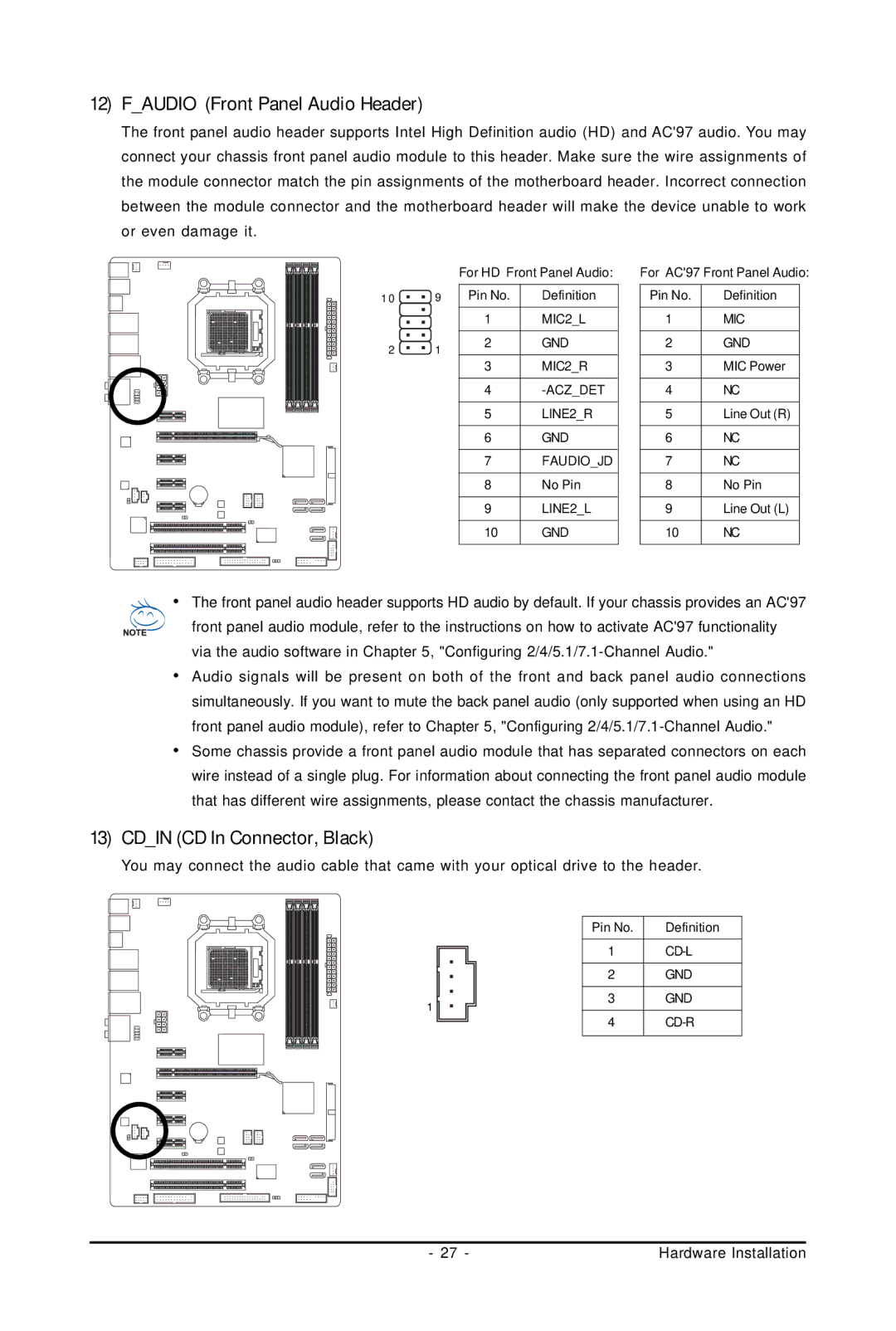
Faudio Front Panel Audio Header
Cdin CD In Connector, Black
Spdifout S/PDIF Out Header
Spdifin S/PDIF In Header, Red
17 F1394 Ieee 1394a Header, Gray
FUSB1/FUSB2 USB Headers, Yellow
Coma Serial Port Header
LPT Parallel Port Header
Clrcmos Clearing Cmos Jumper
CI Chassis Intrusion Header
GA-MA770T-UD3P Motherboard
Bios Setup
Logo Screen Default Post Screen
Startup Screen
Function Keys
Main Menu Help
Sample Bios Version F1b
Bios Setup Program Function Keys
Main Menu
Load Fail-Safe Defaults
Standard Cmos Features
Advanced Bios Features
Power Management Setup
Advanced Clock Calibratioin
MB Intelligent TweakerM.I.T
CPU Clock Ratio
Advanced Clock Calibration
Value All Cores
Value Core 0, Value Core 1, Value Core 2, Value Core
Dram Configuration
DCTs Mode
DDR3 Timing Items
Write Recovery Time
RAS to CAS R/W Delay
1T/2T Command Timing
TwTr Command Delay
DDR VTT Voltage Control
CPU Voltage Control
Normal CPU Vcore
Dram Voltage Control
IDE Channel 2, 3 Master/Slave
Date
Time
IDE Channel 0, 1 Master/Slave
Memory
Floppy 3 Mode Support
Drive a
Halt On
Virtualization
Hard Disk Boot Priority
First/Second/Third Boot Device
Password Check
Full Screen Logo Show
Away Mode
Backup Bios Image to HDD
HDD S.M.A.R.T. Capability
Onboard LAN Function
Onboard LAN Boot ROM
OnChip IDE Channel
Onboard 1394 Function
When a Cable Problem Occurs
Smart LAN LAN Cable Diagnostic Function
When No LAN Cable Is Attached
When LAN Cable Is Functioning Normally
Onboard Audio Function
OnChip Sata Type SATA20~SATA23 connectors
OnChip Sata Port4/5 Mode SATA24/SATA25 connectors
OnChip Sata Controller
ECP Mode Use DMA
Parallel Port Mode
Modem Ring Resume
USB Wake Up from S3
Power-On by Alarm
Power On By Mouse
Power On By Keyboard
KB Power on Password
Case Opened
Reset Case Open Status
CPU/SYSTEM/POWER FAN Fail Warning
Current System/CPU Temperature
Current CPU/SYSTEM/POWER FAN Speed RPM
CPU Warning Temperature
Load Optimized Defaults
Load Fail-Safe Defaults
User Password
Supervisor Password
Exit Without Saving
Save & Exit Setup
Installing Chipset Drivers
Drivers Installation
Technical Manuals
Application Software
System
Contact
Download Center
Before You Begin
Xpress Recovery2
Installation and Configuration
Installing Windows Vista and Partitioning the Hard Drive
Using the Backup Function in Xpress Recovery2
Accessing Xpress Recovery2
Using the Restore Function in Xpress Recovery2
Removing the Backup
Exiting Xpress Recovery2
What is Q-FlashTM?
Bios Update Utilities
Updating the Bios with the Q-Flash Utility
What is DualBIOSTM?
Updating the Bios
Page
Updating the Bios with the @BIOS Utility
Using @BIOS
After Updating the Bios
EasyTune 6 Interface Tabs Information
EasyTune
Easy Energy Saver Interface Meter Mode
Meter Mode Button Information Table
Easy Energy Saver
Total Mode
Total Mode Button Information Table
Stealth Mode
Directions for using Q-Share
Share
Options Descriptions
System Restore
Time Repair
Preference Screen
Installing Sata hard drives in your computer
Configuring Sata Hard Drives
Configuring the Onboard Sata Controller
To configure Sata hard drives, follow the steps below
RAID
Configuring Sata controller mode in Bios Setup
Main Menu
Configuring RAID set in RAID Bios
Drives Assignments
Create Arrays Manually
View Drives Assignments
View Drive Assignments
View LD Definition Menu
Delete an Array
Making a Sata RAID/AHCI Driver Diskette for Windows XP
Required for Ahci and RAID Mode
Installing Windows XP
Installing the Sata RAID/AHCI Driver and Operating System
\BootDrv\SB750V\LH
Installing Windows Vista
Page
Rebuilding an Array
High Definition Audio HD Audio
Configuring Audio Input and Output
Configuring 2/4/5.1/7.1-Channel Audio
Configuring Speakers
Configuring Sound Effect
Activating an AC97 Front Panel Audio Module
Muting the Back Panel Audio For HD Audio Only
Pdif
Configuring S/PDIF In/Out
Installing the S/PDIF In Cable
Configuring S/PDIF
Connecting a S/PDIF Out Cable
Configuring S/PDIF Out
Pdif Out
Configuring Microphone Recording
Enabling Stereo Mix
Using the Sound Recorder
Recording Sound
Playing the Recorded Sound
Frequently Asked Questions
Troubleshooting
Start
Troubleshooting Procedure
END
Our Commitment to Preserving the Environment
Weee Symbol Statement
Regulatory Statements
Regulatory Notices
China Restriction of Hazardous Substances Table
GA-MA770T-UD3P Motherboard
Appendix
GA-MA770T-UD3P Motherboard
G.B.T. INC USA Mexico
Contact Us
Gigabyte Global Service System