4-4 Installation of Front I/O Panel
Incorrect connector installation may possibly burn out the motherboard and other components. Be sure to observe the instructions on installation in the manual. Any loss arising from nonobservance of the proper operation provided is not covered by the warranty.
Different motherboards may have different installation positions. For detailed instructions, please refer to the instructions supplied by the motherboard manufacturer.
The front panel consists of (1) 2 USB 2.0 / 1 IEEE 1394 / 1 audio
(2) a basic casing power switch control cable kit
Required tool: None
(1) 2 USB 2.0 / 1 IEEE 1394 / 1 Audio
USB 2.0 Connector | Pin | Definition | Pin | Definition |
| 1 | Power | 6 | USB Dy+ |
| 2 | Power | 7 | GND |
| 3 | USB Dx- | 8 | GND |
| 4 | USB Dy- | 9 |
|
| 5 | USB Dx+ | 10 | USB Over Current |
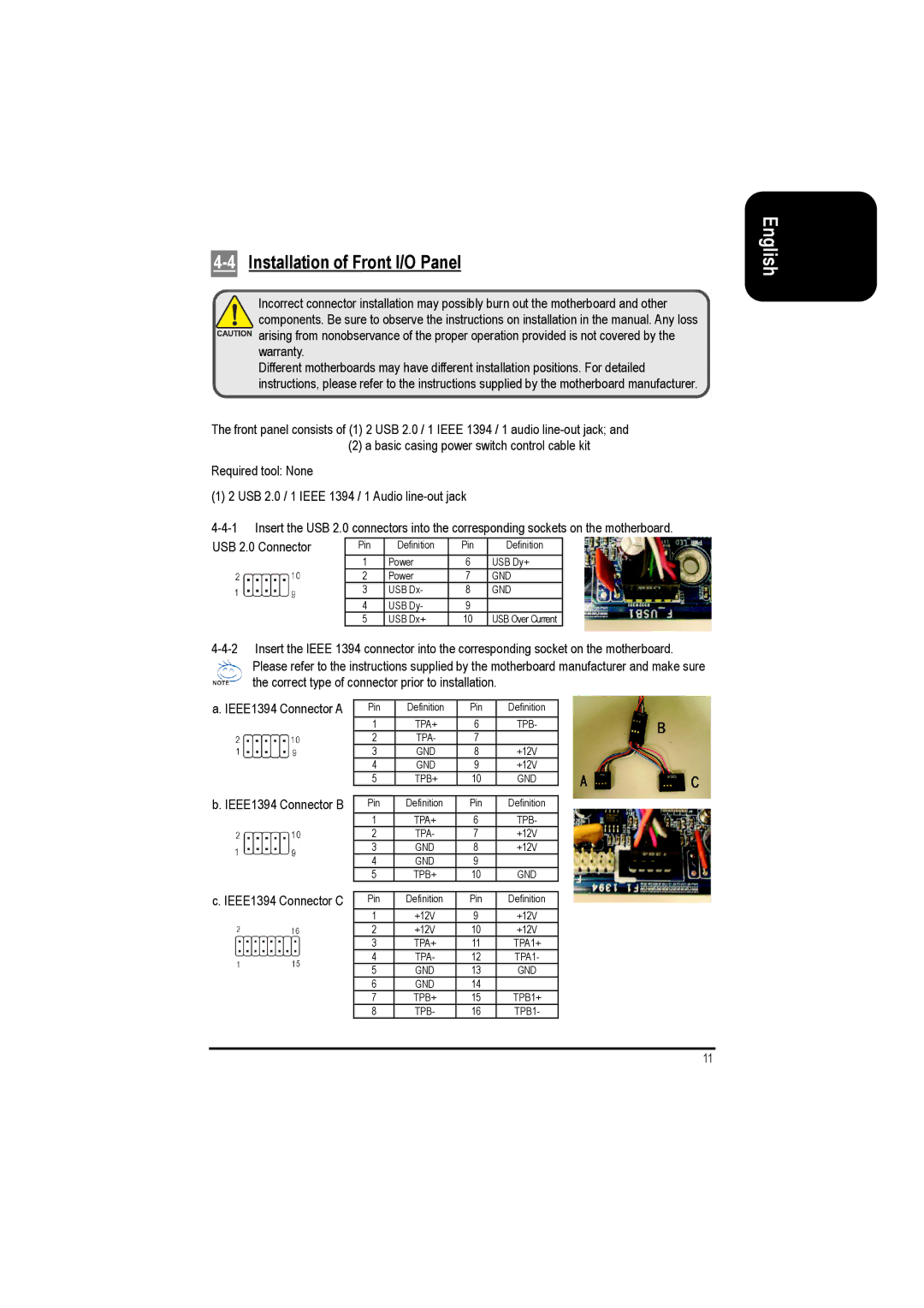
Please refer to the instructions supplied by the motherboard manufacturer and make sure the correct type of connector prior to installation.
a. IEEE1394 Connector A | Pin | Definition | Pin | Definition |
| 1 | TPA+ | 6 | TPB- |
| 2 | TPA- | 7 |
|
| 3 | GND | 8 | +12V |
| 4 | GND | 9 | +12V |
| 5 | TPB+ | 10 | GND |
b. IEEE1394 Connector B |
|
|
|
|
Pin | Definition | Pin | Definition | |
| 1 | TPA+ | 6 | TPB- |
| 2 | TPA- | 7 | +12V |
| 3 | GND | 8 | +12V |
| 4 | GND | 9 |
|
| 5 | TPB+ | 10 | GND |
c. IEEE1394 Connector C |
|
|
|
|
Pin | Definition | Pin | Definition | |
| 1 | +12V | 9 | +12V |
| 2 | +12V | 10 | +12V |
| 3 | TPA+ | 11 | TPA1+ |
| 4 | TPA- | 12 | TPA1- |
| 5 | GND | 13 | GND |
| 6 | GND | 14 |
|
| 7 | TPB+ | 15 | TPB1+ |
| 8 | TPB- | 16 | TPB1- |
11
English