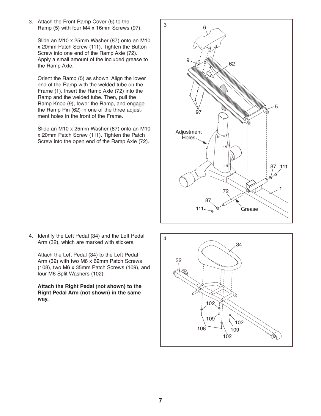
3. Attach the Front Ramp Cover (6) to the | 3 | 6 |
|
| |
Ramp (5) with four M4 x 16mm Screws (97). |
|
| |||
Slide an M10 x 25mm Washer (87) onto an M10 |
|
|
|
|
|
x 20mm Patch Screw (111). Tighten the Button |
|
|
|
|
|
Screw into one end of the Ramp Axle (72). |
|
|
|
|
|
Apply a small amount of the included grease to |
| 9 |
| 62 |
|
the Ramp Axle. |
|
|
| ||
Orient the Ramp (5) as shown. Align the lower |
|
|
|
|
|
end of the Ramp with the welded tube on the |
|
|
|
|
|
Frame (1). Insert the Ramp Axle (72) into the |
|
|
|
|
|
Ramp and the welded tube. Then, pull the |
|
|
|
|
|
Ramp Knob (9), lower the Ramp, and engage |
|
|
| 5 |
|
the Ramp Pin (62) in one of the three adjust- |
| 97 |
|
| |
ment holes in the front of the Frame. |
|
|
|
| |
Slide an M10 x 25mm Washer (87) onto an M10 |
| Adjustment |
|
|
|
x 20mm Patch Screw (111). Tighten the Patch |
|
|
|
| |
Screw into the open end of the Ramp Axle (72). |
| Holes |
|
|
|
|
|
|
| 87 | 111 |
|
| 111 87 | 72 | 1 | |
|
| Grease |
| ||
4. Identify the Left Pedal (34) and the Left Pedal | 4 |
|
| 34 |
|
Arm (32), which are marked with stickers. |
|
|
| ||
Attach the Left Pedal (34) to the Left Pedal |
| 32 |
|
|
|
Arm (32) with two M6 x 62mm Patch Screws |
|
|
|
| |
(108), two M6 x 35mm Patch Screws (109), and |
|
|
|
|
|
four M6 Split Washers (102). |
|
|
|
|
|
Attach the Right Pedal (not shown) to the |
|
|
|
|
|
Right Pedal Arm (not shown) in the same |
|
| 102 |
|
|
way. |
|
|
|
| |
|
| 108 | 109 | 102 |
|
|
|
| 102109 |
| |
| 7 |
|
|
|
|
