SPEED TAP ADJUSTMENTS FOR INDOOR BLOWER MOTOR
PSC Motor
Adjust the CFM by changing the speed tap of the indoor blower motor at the EBTDR “COM” connection with one of the speed taps on “M1” or “M2”.
X-13 Motor
Adjust the CFM by changing the 24V low voltage lead at the speed terminal block on the motor.
REFRIGERANT CHARGE CHECKS
After completing airflow measurements and adjustments, the unit’s refrigerant charge must be checked. The unit is factory charged based on 400 CFM per ton at minimum ESP per AHRI test condi- tions (generally between .15
For charging in the warmer months, 8
A superheat charge chart is available for other operating condi- tions. Use it to provide the correct superheat at the conditions the unit is being charged at.
After superheat is adjusted it is recommended to check unit sub- cooling at the condenser coil liquid line out. In most operating conditions 10 - 15ºF of
SUPERHEAT = SUCTION LINE TEMP - SAT. SUCTION TEMP
SATURATED SUCTION PRESSURE
TEMPERATURE CHART
Suction | Saturated Suction |
Pressure | Temperature °F |
PSIG | |
50 | 1 |
52 | 3 |
54 | 4 |
56 | 6 |
58 | 7 |
60 | 8 |
62 | 10 |
64 | 11 |
66 | 13 |
68 | 14 |
70 | 15 |
72 | 16 |
71 | 17 |
76 | 19 |
78 | 20 |
80 | 21 |
SUBCOOLING = SAT. LIQUID TEMP. - LIQUID LINE TEMP.
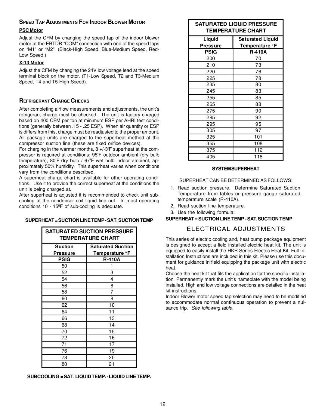
SATURATED LIQUID PRESSURE
TEMPERATURE CHART
Liquid | Saturated Liquid |
Pressure | Temperature °F |
PSIG | |
200 | 70 |
210 | 73 |
220 | 76 |
225 | 78 |
235 | 80 |
245 | 83 |
255 | 85 |
265 | 88 |
275 | 90 |
285 | 92 |
295 | 95 |
305 | 97 |
325 | 101 |
355 | 108 |
375 | 112 |
405 | 118 |
SYSTEMSUPERHEAT
SUPERHEAT CAN BE DETERMINED AS FOLLOWS:
1.Read suction pressure. Determine Saturated Suction Temperature from tables or pressure gauge saturated temperature scale
2.Read suction line temperature.
3.Use the following formula:
SUPERHEAT = SUCTION LINE TEMP - SAT. SUCTION TEMP
ELECTRICAL ADJUSTMENTS
This series of electric cooling and, heat pump package equipment is designed to accept a field installed electric heat kit. The unit is equipped to easily install the HKR Series Electric Heat Kit. Full In- stallation Instructions are included in this kit. Please use this docu- ment for guidance in field equipping the package unit with electric heat.
Choose the heat kit that fits the application for the specific installa- tion. Permanently mark the unit’s nameplate with the model being installed. High and low voltage connections are detailed in the heat kit instructions.
Indoor Blower motor speed tap selection may need to be modified to accommodate normal continuous operation to prevent a nui- sance trip. See following table.
12