WIRING
NOTE: All wiring should be made in accordance with the National Electrical Code.
Consult your local Power Company to determine the availability of sufficient power to operate the unit. Check the voltage, frequency, and phase at the power supply to ensure it corresponds to the unit’s
RATED VOLTAGE REQUIREMENT.
In accordance with the N.E.C. or local codes, install a branch cir- cuit fused disconnect near the unit. Determine wire sizes and overcurrent protection from the unit nameplate ampacity and in accordance with the Minimum Filter Size or the N.E.C. The wiring should never be sized smaller than is recommended by either of these two sources.
Fuses smaller than that recommended on the rating plate could result in unnecessary fuse failure or service calls. The use of protective devices of larger size than indicated could result in ex- tensive damage to the equipment. The manufacturer bears no responsibility for damage caused to equipment as result of the use of larger than is recommended size protective devices.
All units have undergone a run test prior to packaging for ship- ment. This equipment has been started at minimum rated voltage and checked for satisfactory operation. Do not attempt to operate this unit if the voltage is not within the minimum and maximum voltages shown on nameplate.
All exterior wiring must be within approved weatherproof conduit. The unit must be permanently grounded in accordance with local codes, or in absence of local codes, with N.E.C ANSI/ NFPA NO.
Fuses or HACR type circuit breakers may be used where codes permit.
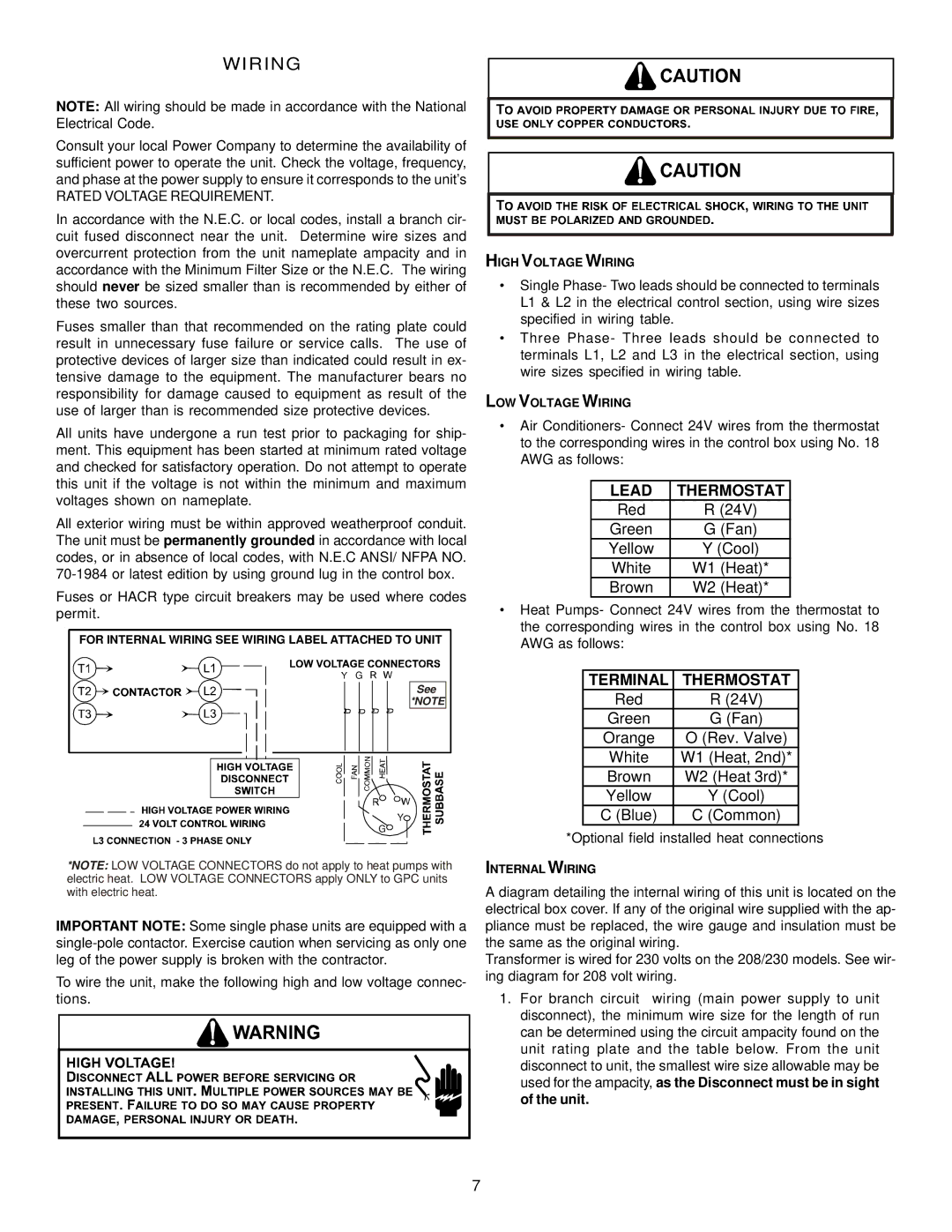
FOR INTERNAL WIRING SEE WIRING LABEL ATTACHED TO UNIT
G
See *NOTE
G![]()
*NOTE: LOW VOLTAGE CONNECTORS do not apply to heat pumps with electric heat. LOW VOLTAGE CONNECTORS apply ONLY to GPC units with electric heat.
IMPORTANT NOTE: Some single phase units are equipped with a
To wire the unit, make the following high and low voltage connec- tions.
HIGH VOLTAGE WIRING
•Single Phase- Two leads should be connected to terminals L1 & L2 in the electrical control section, using wire sizes specified in wiring table.
•Three Phase- Three leads should be connected to terminals L1, L2 and L3 in the electrical section, using wire sizes specified in wiring table.
LOW VOLTAGE WIRING
•Air Conditioners- Connect 24V wires from the thermostat to the corresponding wires in the control box using No. 18 AWG as follows:
LEAD | THERMOSTAT |
Red | R (24V) |
Green | G (Fan) |
Yellow | Y (Cool) |
White | W1 (Heat)* |
Brown | W2 (Heat)* |
•Heat Pumps- Connect 24V wires from the thermostat to the corresponding wires in the control box using No. 18 AWG as follows:
TERMINAL | THERMOSTAT |
Red | R (24V) |
Green | G (Fan) |
Orange | O (Rev. Valve) |
White | W1 (Heat, 2nd)* |
Brown | W2 (Heat 3rd)* |
Yellow | Y (Cool) |
C (Blue) | C (Common) |
*Optional field installed heat connections
INTERNAL WIRING
A diagram detailing the internal wiring of this unit is located on the electrical box cover. If any of the original wire supplied with the ap- pliance must be replaced, the wire gauge and insulation must be the same as the original wiring.
Transformer is wired for 230 volts on the 208/230 models. See wir- ing diagram for 208 volt wiring.
1.For branch circuit wiring (main power supply to unit disconnect), the minimum wire size for the length of run can be determined using the circuit ampacity found on the unit rating plate and the table below. From the unit disconnect to unit, the smallest wire size allowable may be used for the ampacity, as the Disconnect must be in sight of the unit.
7