LaserSpeed
Installing the System
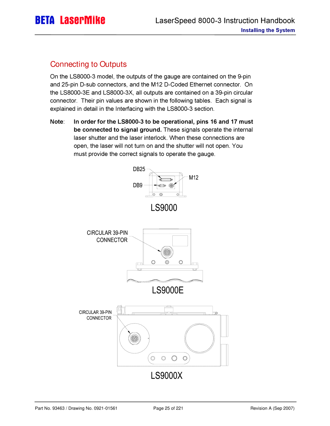
Connecting to Outputs
On the
Note: In order for the
Part No. 93463 / Drawing No. | Page 25 of 221 | Revision A (Sep 2007) |
LaserSpeed
Installing the System
On the
Note: In order for the
Part No. 93463 / Drawing No. | Page 25 of 221 | Revision A (Sep 2007) |