Laser LS8000-3 manual DB9 Connector, RS-422 Transmit +/- and Receive +/- Pins

Models: LS8000-3

1 221
Download 221 pages 9.92 Kb
Page 56
Image 56

LaserSpeed 8000-3 Instruction Handbook

Interfacing with the
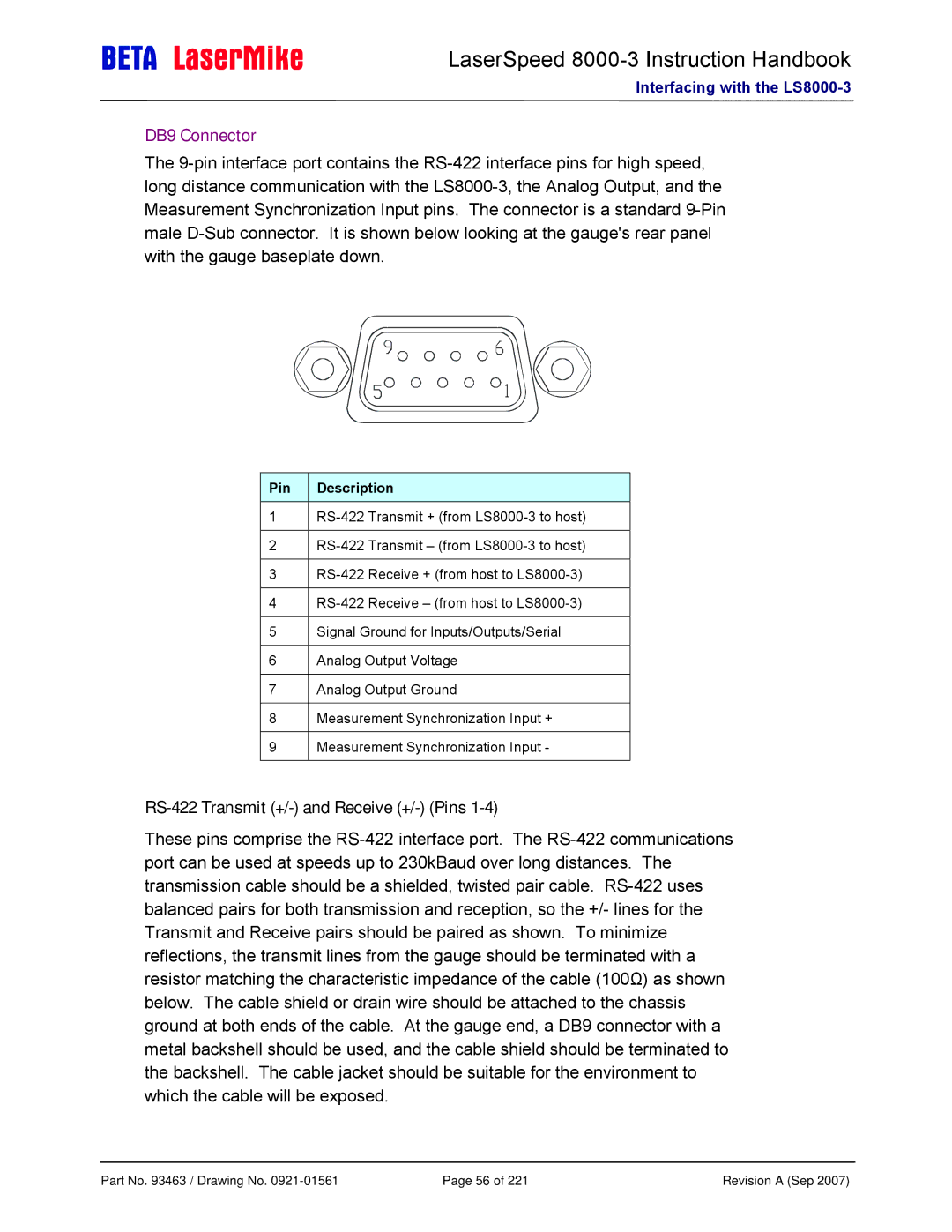
 LS8000-3

DB9 Connector

The 9-pin interface port contains the RS-422 interface pins for high speed, long distance communication with the LS8000-3, the Analog Output, and the Measurement Synchronization Input pins. The connector is a standard 9-Pin male D-Sub connector. It is shown below looking at the gauge's rear panel with the gauge baseplate down.

Pin

Description


1RS-422 Transmit + (from LS8000-3 to host)

2RS-422 Transmit – (from LS8000-3 to host)

3RS-422 Receive + (from host to LS8000-3)

4RS-422 Receive – (from host to LS8000-3)

5Signal Ground for Inputs/Outputs/Serial

6Analog Output Voltage

7Analog Output Ground

8Measurement Synchronization Input +

9Measurement Synchronization Input -

RS-422 Transmit (+/-) and Receive (+/-) (Pins 1-4)

These pins comprise the RS-422 interface port. The RS-422 communications port can be used at speeds up to 230kBaud over long distances. The transmission cable should be a shielded, twisted pair cable. RS-422 uses balanced pairs for both transmission and reception, so the +/- lines for the Transmit and Receive pairs should be paired as shown. To minimize reflections, the transmit lines from the gauge should be terminated with a resistor matching the characteristic impedance of the cable (100Ω) as shown below. The cable shield or drain wire should be attached to the chassis ground at both ends of the cable. At the gauge end, a DB9 connector with a metal backshell should be used, and the cable shield should be terminated to the backshell. The cable jacket should be suitable for the environment to which the cable will be exposed.

Part No. 93463 / Drawing No. 0921-01561

Page 56 of 221

Revision A (Sep 2007)

Page 56
Image 56
Laser LS8000-3 manual DB9 Connector, RS-422 Transmit +/- and Receive +/- Pins